► HOT SURFACE IGNITER (HSI)
(-)GPJ / (-)GLJ / (-)GVJ models
continue to use a silicon carbide in
ceramic body hot surface igniter to
light the burners. When energized the
HSI heats to approximately 2600°F. It
mounts between two burners on one
side of the burner tray.
NOTE: Earlier dedicated upflow and
dedicated down/low models have
used either standing pilot or hot
suface ignition.
FIGURE 9
HOT SURFACE IGNITER
C
•
►
a
►
DIRECT SPARK IGNITER (OSI)
Current production (-)GPH / (-)GLH
models now use direct spark ignition.
An igniter sparks to light the burners
directly. This minimizes ignition time
and electric current draw on start up.
The spark stops as soon as the flame
sensor detects burner ignition.
FIGURE 10
DIRECT SPARK IGNITER
LIMIT SWITCHES
Each unit comes with a high
temperature limit control switch to
monitor air temperature in the heat
exchanger area. If the temperature
rises above its set point, the limit
contacts open and shut down the
burners. In addition downflow and
horizontal units have an additional
heat assisted limit control on the
blower housing. It prevents excessive
temperatures in the blower
compartment and at the filters.
OVER TEMPERATURE SWITCHES
Over temperature switches prevent
overheating conditions in the control
compartment caused by inadequate
combustion air. The switch mounts
just above the burners on the furnace
center panel on upflow and down/low
models. There is one above the
burners and one at each end of the
burner brackets on upflow/horizontal
models. The dedicated horizontal
units only have two at the ends of the
burner side brackets.
FIGURE 11
OVER TEMPERATURE
SWITCHES
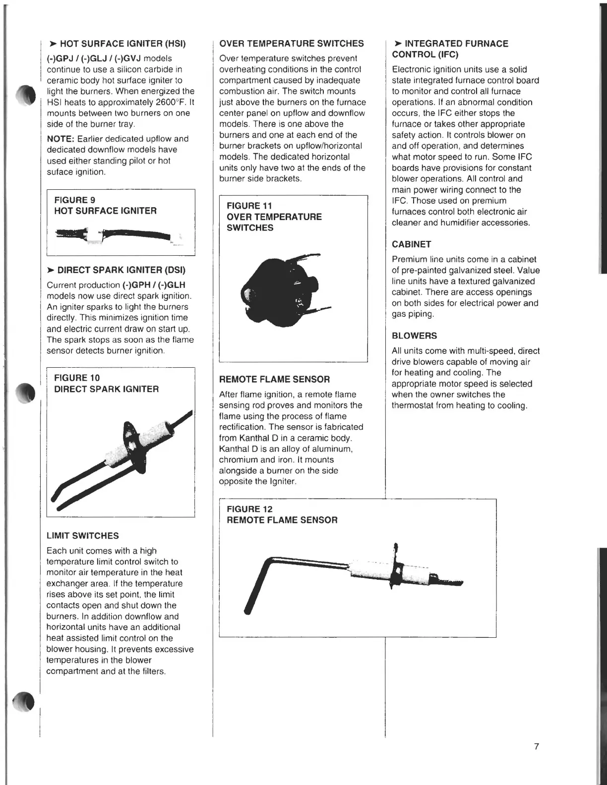
REMOTE FLAME SENSOR
After flame ignition, a remote flame
sensing rod proves and monitors the
flame using the process of flame
rectification. The sensor is fabricated
from Kanthal Din a ceramic body.
Kanthal D is an alloy of aluminum,
chromium and iron. It mounts
alongside a burner on the side
opposite the Igniter.
FIGURE 12
REMOTE FLAME SENSOR
►
INTEGRATED
FURNACE
CONTROL (IFC)
Electronic ignition units use a solid
state integrated furnace control board
to monitor and control all furnace
operations. If an abnormal condition
occurs, the IFC either stops the
furnace or takes other appropriate
safety action. It controls blower on
and off operation, and determines
what motor speed to run. Some IFC
boards have provisions for constant
blower operations. All control and
main power wiring connect to the
IFC. Those used on premium
furnaces control both electronic air
cleaner and humidifier accessories.
CABINET
Premium line units come in a cabinet
of pre-painted galvanized steel. Value
line units have a textured galvanized
cabinet. There are access openings
on both sides for electrical power and
gas piping.
BLOWERS
All units come with multi-speed, direct
drive blowers capable of moving air
for heating and cooling. The
appropriate motor speed is selected
when the owner switches the
thermostat from heating to cooling.
i+----·-- ..ktr,,.;-~-~-~.-.~'I.
7