position of the screws marked SW1
and SW2. Use Figure 48 to set the
blower off timing.
The blower off timing on the UTEC
control depends on the position of
three small switches. Adjust the
blower off time delay by setting these
switches.
BLOWER WIRING CONNECTIONS
A CAUTION: DISCONNECT THE
ELECTRICAL SUPPLY TO THE
FURNACE BEFORE ATTEMPTING
TO CHANGE THE BLOWER
SPEED. FAILURE TO DISCONNECT
ELECTRICAL POWER MAY
RESULT IN PROPERTY DAMAGE
FROM FIRE OR PERSONAL
INJURY OR DEATH FROM
ELECTRICAL SHOCK.
The furnace control board, either
standing pilot or hot surface ignition,
comes wired with the heating speed
tap connected to the terminal marked
"HEAT" and cooling speed tap
connected to the terminal marked
"COOL." Any unused motor speed
taps connect to terminals marked
"M1" and "M2."
The motor speed taps may be
changed to fit the needs of a specific
installation. Reconnect any unused
motor leads to terminals "M1" and
"M2." Check the motor speed tap wire
color for the specific speed as
marked on the wiring diagram.
FIELD INSTALLED ACCESSORIES
1. Connect the line voltage wiring of
an electronic air cleaner to the
screw terminal "EAC" and neutral
on the Hot Surface Ignition
control boards.This powers the
EAC whenever the main blower
operates.
2. Connect the line voltage wiring of
a Humidifier to the screw
terminal "HUM" and neutral on
the Hot Surface Ignition control
boards. This powers a humidifier
whenever the burner is on and
the main blower operates in the
heating mode.
NOTE: The maximum amperage for
each option is 1.0 amps.
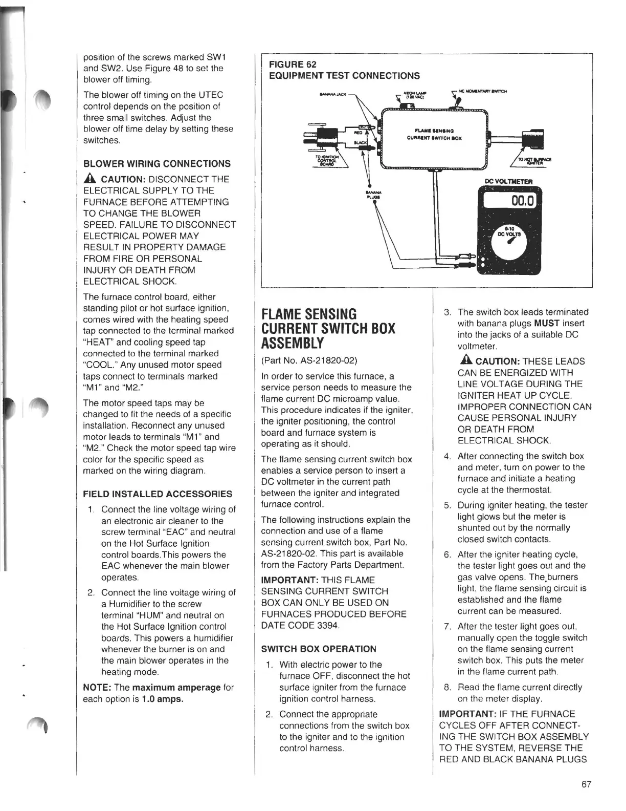
FIGURE62
EQUIPMENT TEST CONNECTIONS
l'I.AIIINHIIHQ
CURAaNT IWITC>< IIOX
-
.......
FLAMESENSING
CURRENTSWITCHBOX
ASSEMBLY
(Part No. AS-21820-02)
In order to service this furnace, a
service person needs to measure the
flame current DC microamp value.
This procedure indicates if the igniter,
the igniter positioning, the control
board and furnace system is
operating as it should.
The flame sensing current switch box
enables a service person to insert a
DC voltmeter in the current path
between the igniter and integrated
furnace control.
The following instructions explain the
connection and use of a flame
sensing current switch box, Part No.
AS-21820-02. This part is available
from the Factory Parts Department.
IMPORTANT: THIS FLAME
SENSING CURRENT SWITCH
BOX CAN ONLY BE USED ON
FURNACES PRODUCED BEFORE
DATE CODE 3394.
SWITCH BOX OPERATION
1. With electric power to the
furnace OFF, disconnect the hot
surface igniter from the furnace
ignition control harness.
2. Connect the appropriate
connections from the switch box
to the igniter and to the ignition
control harness.
'IU~
3. The switch box leads terminated
with banana plugs MUST insert
into the jacks of a suitable DC
voltmeter.
A CAUTION: THESE LEADS
CAN BE ENERGIZED WITH
LINE VOLTAGE DURING THE
IGNITER HEAT UP CYCLE.
IMPROPER CONNECTION CAN
CAUSE PERSONAL INJURY
OR DEATH FROM
ELECTRICAL SHOCK.
4. After connecting the switch box
and meter, turn on power to the
furnace and initiate a heating
cycle at the thermostat.
5. During igniter heating, the tester
light glows but the meter is
shunted out by the normally
closed switch contacts.
6. After the igniter heating cycle,
the tester light goes out and the
gas valve opens. The.burners
light, the flame sensing circuit is
established and the flame
current can be measured.
7. After the tester light goes out,
manually open the toggle switch
on the flame sensing current
switch box. This puts the meter
in the flame current path.
8. Read the flame current directly
on the meter display.
IMPORTANT: IF THE FURNACE
CYCLES OFF AFTER CONNECT-
ING THE SWITCH BOX ASSEMBLY
TO THE SYSTEM, REVERSE THE
RED AND BLACK BANANA PLUGS
67