TWINNING INSTRUCTIONS
Twinning or parallel operation of two
furnaces, installed side by side,
connected by a common duct system
and controlled by a single thermostat
can be done with
UTEC1012-925
integrated furnace controls using this
wiring kit. The addition of the two
blower compartment door interlock
switches in this kit assures that all
electrical power to both furnaces is
deenergized if either furnace blower
compartment door is not in place.
The additional switch, located in the
remote furnace is in series to the
furnace electrical supply as shown in
the wiring diagram, Figure 124, page
114. A line voltage connecting wire
between the electronic air cleaner
(EAC) terminals on both furnace
control boards assures simultaneous
indoor blower operation. The
switches, line voltage wiring and
mounting materials are included in
this kit. The thermostat and low
voltage (24 VAC) control wiring
materials are normal field supplied
items.
All electrical work must conform with
the requirements of local codes and
ordinances and the National Electric
Code ANSI/ NFPA- No. 70 latest
edition or the Canadian Electrical
Code Part 1 - CSA Standard C22.1
for Canadian installations.
ELECTRICAL WIRING
A WARNING:TURN OFF
ELECTRIC POWER AT THE FUSE
BOX OR SERVICE PANEL BEFORE
MAKING ANY ELECTRICAL CON-
NECTIONS. FAILURE TO DO SO
COULD RESULT IN AN ELECTRI-
CAL SHOCK HAZARD, PROPERTY
DAMAGE AND/OR PERSONAL
INJURY.
A WARNING: BOTH FURNACE
CABINETS MUST BE PERMA-
NENTLY GROUNDED. A GROUND
SCREW IN THE JUNCTION BOX IS
FOR THIS PURPOSE. GROUND
CONNECTIONS MUST BE
COMPLETED BEFORE MAKING
LINE VOLTAGE CONNECTIONS.
FAILURE TO DO SO COULD
RESULT IN AN ELECTRICAL
SHOCK HAZARD, PROPERTY
DAMAGE AND/OR PERSONAL
INJURY.
THE FURNACES MUST BE
INSTALLED SO THE ELECTRICAL
COMPONENTS ARE PROTECTED
FROM WATER.
A WARNING: ELECTRICAL
POWER MUST BE SUPPLIED TO
BOTH FURNACES FROM THE
SAME SEPARATE BRANCH
CIRCUIT. FAILURE TO DO SO
COULD RESULT IN EXPOSING
THE FURNACE CONTROLS TO
AN OVER VOLT AGE (230 VAC)
CONDITION. THIS COULD RESULT
IN DESTRUCTION OF THE
CONTROLBOARDS,PROPERTY
DAMAGE AND/OR PERSONAL
INJURY.
A WARNING: L 1 (HOT) AND
NEUTRAL POLARITY MUST BE
OBSERVED WHEN MAKING FIELD
CONNECTIONS TO THE FUR-
NACES. FAILURE TO DO SO
COULD RESULT IN A DIRECT
SHORT VIA THE CONNECTION
BETWEEN THE "EAC" TERMINALS
WHEN THE INDOOR BLOWER
RELAY CLOSES. THIS COULD
RESULT IN DESTRUCTION OF THE
CONTROLBOARDS,PROPERTY
DAMAGE AND/OR PERSONAL
INJURY.
The furnaces must be on the same
branch circuit with adequate ampacity
and overcurrent protections. Do not
use existing lighting or other circuits.
NOTE: See the furnace rating plates
for motor H.P. ratings, electrical
characteristics, and amp draw.
NOTE: Use time delay fuses or circuit
breakers.
NOTE: Use the wiring diagram,
Figure 124, page 114 when installing
this twinning kit.
INSTALLATION PRO
CEDURES
Install the furnaces si de by side and
connect to the comm on supply and
return duct system. F ollow the
r
furnace installation in
structions. It
may be convenient to
convert the
right hand furnace to right side gas
and electrical supply.
1. Install the two bo xes from the kit
in the furnace jac kets using the
screws provided before locating
the furnaces. Re move the
knockouts as req uired. Insert the
snap bushings a nd plug buttons
while access is a vailable.
2. Identify the furna ces as number
1 and 2 for wiring
purposes. The
wiring diagram ar
bitrarily shows
furnace 1 on the I
eft.
3.
Turn off the elect
rical supply to
both furnaces bet ore making any
electrical connect
ions.
4. Disconnect and r emove the
control transform
er from furnace
2. Remove the bl ack and white
line voltage trans former leads
from the "L 1" and "neutral"
terminals on cont
rol board 2.
Remove only the
red and yellow
transformer lead wires from the
r
"24 VAC" and "C OM" terminals.
5. Remove the blac k wires
connecting the bl
ower door
switch (PBS) and "L 1" on the
control boards in furnaces 1
and 2.
6. Install the switch
es from the kit in
the boxes. Insert each switch in
the rectangular mounting hole.
7. Install the line vol tage
interconnecting wires as shown
in the wiring diag ram. Route the
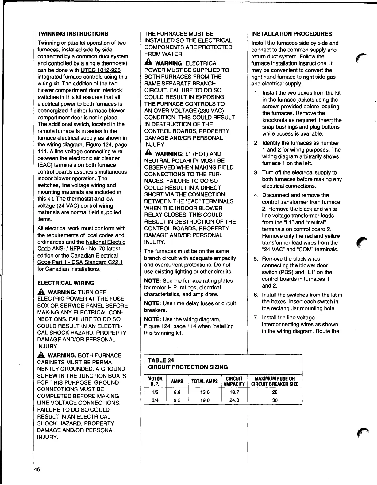
TABLE24
CIRCUIT PROTECTION SIZING
MOTOR
AMPS TOTALAMPS
CIRCUIT
H.P. AMPACITY
1/2 6.8 13.6 18.7
3/4 9.5 19.0
24.8
MAXIMUMFUSEOR
CIRCUITBREAKERSIZE
25
30
46