TO SHUT DOWN THE FURNACE
1. Set the thermostat to its lowest
setting.
2. Shut off the gas to the main
burners and pilot by turning the
knob to the "OFP' position, or by
depressing the gas control lever
and moving it to the "OFP'
position.
IMPORTANT: SHOULD OVER-
HEATING OCCUR OR THE GAS
SUPPLY FAIL TO SHUT OFF, SHUT
OFF THE MANUAL GAS VALVE TO
THE APPLIANCE BEFORE
SHUTTING OFF THE ELECTRICAL
SUPPLY.
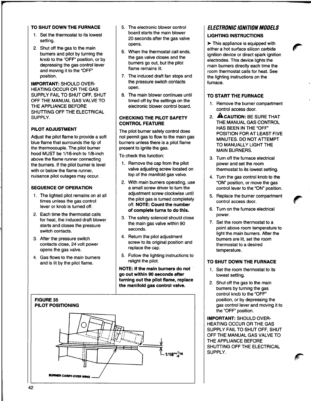
PILOT ADJUSTMENT
Adjust the pilot flame to provide a soft
blue flame that surrounds the tip of
the thermocouple. The pilot burner
hood MUST be 1/16-inch to 1/8-inch
above the flame runner connecting
the burners. If the pilot burner is level
with or below the flame runner,
nuisance pilot outages may occur.
SEQUENCE OF OPERATION
1. The lighted pilot remains on at all
times unless the gas control
lever or knob is turned off.
2. Each time the thermostat calls
for heat, the induced draft blower
starts and closes the pressure
switch contacts.
3. After the pressure switch
contacts close, 24 volt power
opens the gas valve.
4. Gas flows to the main burners
and is lit by the pilot flame.
FIGURE 35
PILOT POSITIONING
5. The electronic blower control
board starts the main blower
20 seconds after the gas valve
opens.
6. When the thermostat call ends,
the gas valve closes and the
burners go out, but the pilot
flame remains lit.
7. The induced draft fan stops and
the pressure switch contacts
open.
8. The main blower continues until
timed off by the settings on the
electronic blower control board.
CHECKING THE PILOT SAFETY
CONTROL FEATURE
The pilot burner safety control does
not permit gas to flow to the main gas
burners unless there is a pilot flame
present to ignite the gas.
To check this function:
1. Remove the cap from the pilot
valve adjusting screw located on
top of the manifold gas valve.
2. With main burners operating, use
a small screw driver to turn the
adjustment screw clockwise until
the pilot gas is turned completely
off.
NOTE: Countthe number
of complete turns to do this.
3. The safety solenoid should close
the main gas valve within 90
seconds.
4. Return the pilot adjustment
screw to its original position and
replace the cap.
5. Follow the lighting instructions to
relight the pilot.
NOTE: If the main burners do not •
go out within 90 seconds after
turning out the pilot flame, replace
the manifold gas control valve.
ELECTRONIC MODELSIGNITION
LIGHTING INSTRUCTIONS
►
This appliance is equipped with
either a hot surface silicon carbide
ignition device or direct spark ignition
electrodes. This device lights the
main burners directly each time the
room thermostat calls for heat. See
the lighting instructions on the
furnace.
TO
START THE FURNACE
1. Remove the burner compartment
control access door.
2. AcAUTION: BE suRE THAT
THE MANUAL GAS CONTROL
HAS BEEN IN THE "OFP'
POSITION FOR AT LEAST FIVE
MINUTES. DO NOT ATTEMPT
TO
MANUALLY LIGHT THE
MAIN BURNERS.
3. Turn off the furnace electrical
power and set the room
thermostat to its lowest setting.
4. Turn the gas control knob to the
"ON" position, or move the gas
control lever to the
"ON" position.
5. Replace the burner compartment
control access door.
r
6. Turn on the furnace electrical
power.
7. Set the room thermostat to a
point above room temperature to
light the main burners. After the
burners are lit, set the room
thermostat to a desired
temperature.
TO SHUT DOWN THE FURNACE
1. Set the room thermostat to its
lowest setting.
2. Shut off the gas to the main
burners by turning the gas
control knob to the "OFP'
position, or by depressing the
gas control lever and moving it to
the "OFF" position.
IMPORTANT: SHOULD OVER-
HEATING OCCUR OR THE GAS
SUPPLY FAIL TO SHUT OFF, SHUT
OFF THE MANUAL GAS VALVE TO
THE APPLIANCE BEFORE
SHUTTING OFF THE ELECTRICAL
SUPPLY.
42