,
TRANSFORMER
The system transformer requires a
115 volt input to the primary winding.
The secondary winding is rated at a
nominal 24 volts, 40 VA output. The
secondary voltage depends upon the
incoming primary voltage. The
transformer is on the blower housing.
When a gas furnace is equipped with
electronic ignition, one side of the
control transformer low voltage circuit
is attached to the furnace case. This
enables the ignition control to
recognize burner operation.
If the thermostat low voltage wires
are connected to the furnace terminal
board and primary power is applied to
the unit, at least one wire can be
powered with 24 volts, even with the
thermostat in the "OFF" position.
Touching any metal surface of the
furnace or condensing unit with a
bare control wire may damage the
transformer secondary winding.
To reduce the probability of
damaging the control transformer
while installing the low voltage control
wiring, turn off or disconnect primary
power to the furnace.
►
Premium units had a trans-
former with a replaceable fuse in one
of the secondary leads. This fuse is a
2.0 amp, slow blow fuse. It protects
low voltage components from any
shorts to ground or other high
amperage conditions. The fuse can
be ordered from the factory Parts
Center with part number 46-22863-
82. Not available with "J" series units.
NOTE: Current units now have this
fuse mounted directly on the furnace
control board.
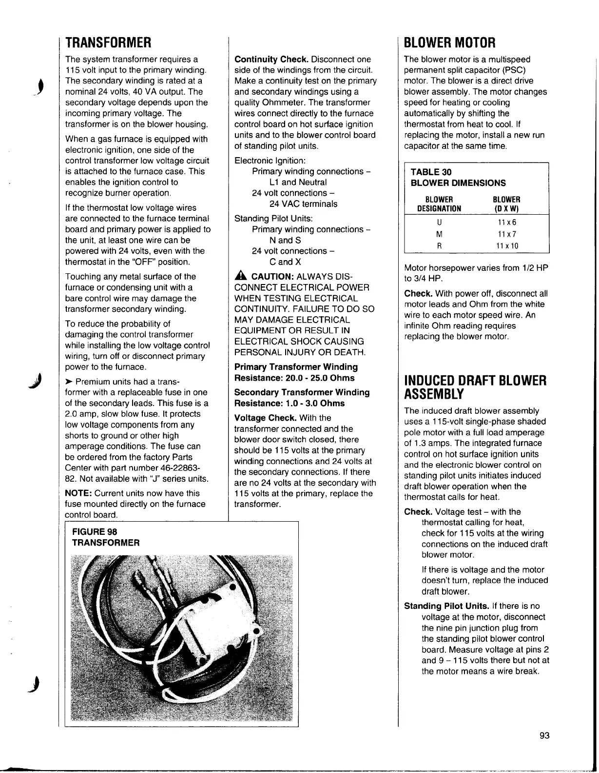
FIGURE98
TRANSFORMER
Continuity Check.
Disconnect one
side of the windings from the circuit.
Make a continuity test on the primary
and secondary windings using a
quality Ohmmeter. The transformer
wires connect directly to the furnace
control board on hot surface ignition
units and to the blower control board
of standing pilot units.
Electronic Ignition:
Primary winding connections -
L 1 and Neutral
24 volt connections -
24 VAC terminals
Standing Pilot Units:
Primary winding connections -
N and S
24 volt connections -
C and X
A CAUTION: ALWAYS DIS-
CONNECT ELECTRICAL POWER
WHEN TESTING ELECTRICAL
CONTINUITY. FAILURE TO DO SO
MAY DAMAGE ELECTRICAL
EQUIPMENT OR RESULT IN
ELECTRICAL SHOCK CAUSING
PERSONAL INJURY OR DEATH.
Primary Transformer Winding
Resistance: 20.0 - 25.0 Ohms
Secondary Transformer Winding
Resistance: 1.0 - 3.0 Ohms
Voltage Check.
With the
transformer connected and the
blower door switch closed, there
should be 115 volts at the primary
winding connections and 24 volts at
the secondary connections. If there
are no 24 volts at the secondary with
115 volts at the primary, replace the
transformer.
BLOWERMOTOR
The blower motor is a multispeed
permanent split capacitor (PSC)
motor. The blower is a direct drive
blower assembly. The motor changes
speed for heating or cooling
automatically by shifting the
thermostat from heat to cool. If
replacing the motor, install a new run
capacitor at the same time.
TABLE 30
BLOWER DIMENSIONS
BLOWER BLOWER
DESIGNATION (DXW)
u
11X 6
M 11x 7
R
11X 10
Motor horsepower varies from 1/2 HP
to 3/4 HP.
Check. With power off, disconnect all
motor leads and Ohm from the white
wire to each motor speed wire. An
infinite Ohm reading requires
replacing the blower motor.
INDUCEDDRAFTBLOWER
ASSEMBLY
The induced draft blower assembly
uses a 115-volt single-phase shaded
pole motor with a full load amperage
of 1.3 amps. The integrated furnace
control on hot surface ignition units
and the electronic blower control on
standing pilot units initiates induced
draft blower operation when the
thermostat calls for heat.
Check. Voltage test - with the
thermostat calling for heat,
check for 115 volts at the wiring
connections on the induced draft
blower motor.
If there is voltage and the motor
doesn't turn, replace the induced
draft blower.
Standing Pilot Units. If there is no
voltage at the motor, disconnect
the nine pin junction plug from
the standing pilot blower control
board. Measure voltage at pins 2
and 9 - 115 volts there but not at
the motor means a wire break.
J
93