FURNACE GAS TRAIN
GAS VALVE
Hot surface ignition furnaces use the
Honeywell VR8005H1060, the
Robertshaw 7200DER-S7 A, or the
White-Rogers 36E37-214 valves.
Standing pilot furnaces use either the
Honeywell VR8200H 1004 or
Robertshaw 7200ER-S7C valves.
Each gas valve is a 24 volt operated
valve. It has ports for measuring
supply and burner manifold pressure.
The valve body contains a pressure
regulator to maintain proper manifold
pressure. The valve can be
converted to use liquified petroleum
(LP) gas by replacing the pressure
regulator spring with the conversion
kit spring. This LP kit spring allows
the regulator to maintain the proper
manifold pressure for LP gas.
NOTE: Order the correct LP
Conversion Kit from the furnace
manufacturer. This operation must
be performed by a qualified
technician.
A manual control is on the valve
body. HSI valves can be set only to
the "ON" or "OFF" position. Standing
pilot valves also have a pilot only
position. Electrical connections are
on the top of the valve body.
FIGURE 103
LP CONVERSION KIT
J
This gas valve is a slow-opening
valve. When the valve energizes, it
takes 6-8 seconds to fully open.
Check. Put the manual control valve
to the "ON" position. With the
thermostat calling for heat, the
induced draft blower operating and
the pressure switch closed, check for
24 volts at the gas valve terminals. If
there is no voltage, be sure the
thermostat is calling and the induced
draft blower has closed the pressure
switch contacts. (Wait 30 seconds
after the inducer starts with hot
surface ignition units.)
With 24 volts at the valve, the valve
should open. Insure that the pilot
flame is proper with standing pilot
units. If there is 24 volts at the valve
and the valve has not opened,
replace the gas valve.
If 24 volts is not at the gas valve,
check for voltage at terminals 4 and 2
on the HSI Furnace Integrated
Control board or terminals 7 and 8 on
the standing pilot blower control
board. If there is voltage at the
control board, but not at the gas
valve, check for a broken wire
connection or open Heat Assisted
Limit Control on Downflow or
Horizontal units.
If there is no voltage at the
appropriate control board terminals,
replace the control board.
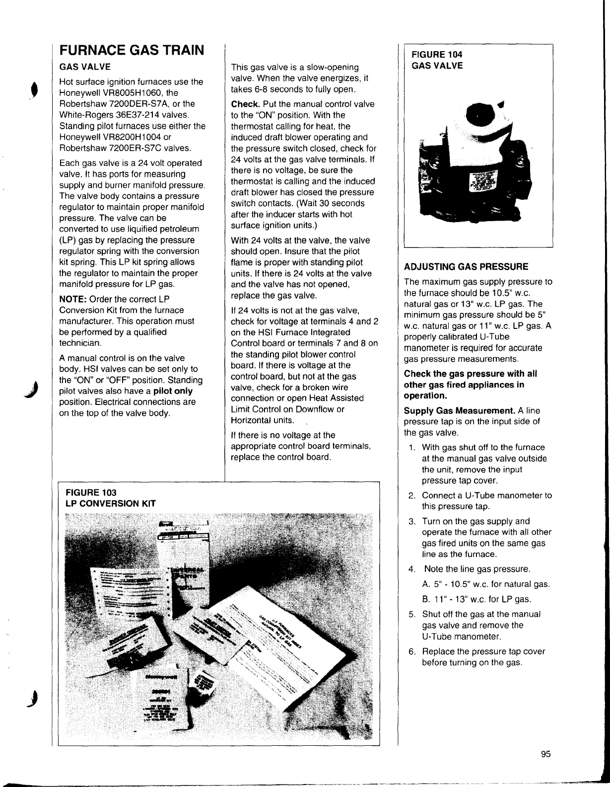
FIGURE 104
GAS VALVE
ADJUSTING GAS PRESSURE
The maximum gas supply pressure to
the furnace should be 10.5'' w.c.
natural gas or 13" w.c. LP gas. The
minimum gas pressure should be 5"
w.c. natural gas or 11" w.c. LP gas. A
properly calibrated U-Tube
manometer is required for accurate
gas pressure measurements.
Check the gas pressure with all
other gas fired appliances in
operation.
Supply Gas Measurement. A line
pressure tap is on the input side of
the gas valve.
1. With gas shut off to the furnace
at the manual gas valve outside
the unit, remove the input
pressure tap cover.
2. Connect a U-Tube manometer to
this pressure tap.
3. Turn on the gas supply and
operate the furnace with all other
gas fired units on the same gas
line as the furnace.
4. Note the line gas pressure.
A. 5" - 10.5" w.c. for natural gas.
8. 11" - 13" w.c. for LP gas.
5. Shut off the gas at the manual
gas valve and remove the
U-Tube manometer.
6. Replace the pressure tap cover
before turning on the gas.
95