y
TRANSFORMER
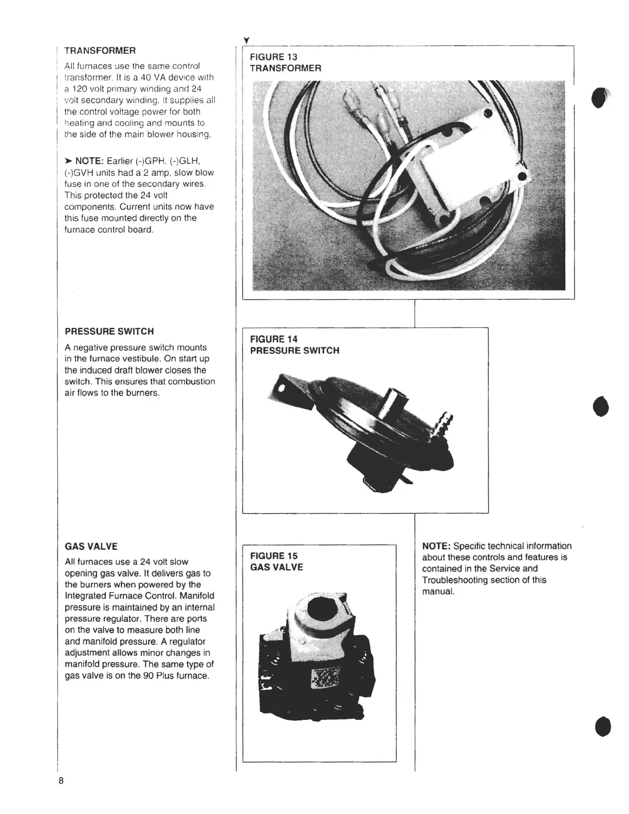
All furnaces use the same control
tmnsformer. It is a 40 VA device with
a 120 volt primary winding and 24
volt secondary winding. It supplies all
the control voltage power for both
heating and cooling and mounts to
the side of the main blower housing.
►
NOTE: Earlier (-)GPH. (-)GLH,
(-)GVH units had a 2 amp, slow blow
fuse in one of the secondary wires.
This protected the 24 volt
components. Current units now have
this fuse mounted directly on the
furnace control board.
PRESSURE SWITCH
A negative pressure switch mounts
in the furnace vestibule. On start up
the induced draft blower closes the
switch. This ensures that combustion
air flows to the burners.
GAS VALVE
All furnaces use a 24 volt slow
opening gas valve. It delivers gas to
the burners when powered by the
Integrated Furnace Control. Manifold
pressure is maintained by an internal
pressure regulator. There are ports
on the valve to measure both line
and manifold pressure. A regulator
adjustment allows minor changes in
manifold pressure. The same type of
gas valve is on the 90 Plus furnace.
I FIGURE 13
TRANSFORMER
I
I
I
I
FIGURE 14
PRESSURE SWITCH
FIGURE 15
GAS VALVE
NOTE: Specific technical information
about these controls and features is
contained in the Service and
Troubleshooting section of this
manual.
•
8