j
...
J
9. Attach the male end of the
sensor wire provided in the kit to
the splice. Attach the other end
of this wire to the sensor. Keep
the wire clear of any sharp metal
edges or hot surfaces. See
Figure 71.
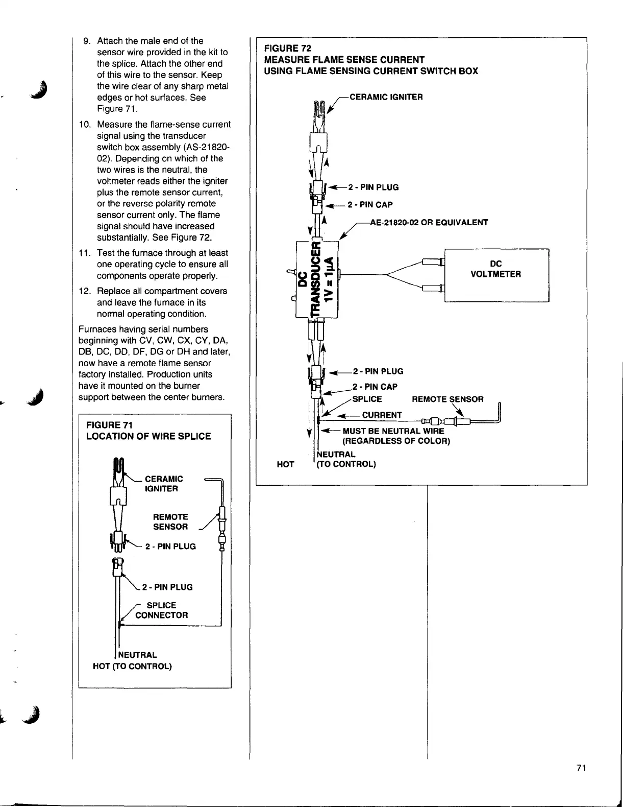
10. Measure the flame-sense current
signal using the transducer
switch box assembly (AS-21820-
02). Depending on which of the
two wires is the neutral, the
voltmeter reads either the igniter
plus the remote sensor current,
or the reverse polarity remote
sensor current only. The flame
signal should have increased
substantially. See Figure 72.
11.
Test the furnace through at least
one operating cycle to ensure all
components operate properly.
12.
Replace all compartment covers
and leave the furnace in its
normal operating condition.
Furnaces having serial numbers
beginning with CV,
cw, ex, CY, DA,
DB, DC, DD, OF, DG or DH and later,
now have a remote flame sensor
factory installed. Production units
have it mounted on the burner
support between the center burners.
FIGURE 71
LOCATION OF WIRE SPLICE
CERAMIC
IGNITER
REMOTE
SENSOR
2- PIN PLUG
2- PIN PLUG
SPLICE
CONNECTOR
NEUTRAL
HOT (TO CONTROL)
FIGURE 72
MEASURE FLAME SENSE CURRENT
USING FLAME SENSING CURRENT SWITCH BOX
rAE-21820-02
DC
OR EQUIVALENT
w
QPII-----<
II
>
p
+
!
..__2
......---2
I/..__
VOLTMETER
81
• PIN PLUG
• PIN CAP
REMOTE SENSOR
t /SPLICE
CURRENT
~
y
~
MUST BE NEUTRAL WIRE
(REGARDLESS OF COLOR)
NEUTRAL
HOT
(TO CONTROL)
71