Ii
control has internal problems and
needs replacement. (The OK LED
flashes if two furnaces are not
twinned properly.)
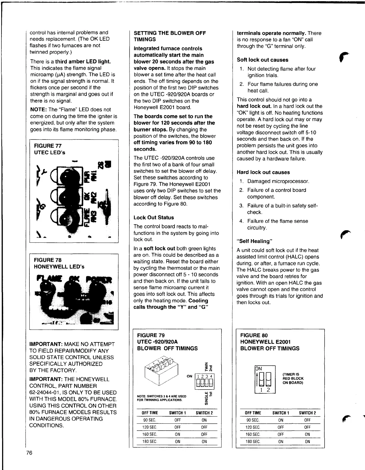
There is a third amber LED light.
This indicates the flame signal
microamp
(µA)strength. The LED is
on if the signal strength is normal. It
flickers once per second if the
strength is marginal and goes out if
there is no signal.
NOTE: The "Flame" LED does not
come on during the time the igniter is
energized, but only after the system
goes into its flame monitoring phase.
FIGURE 77
UTEC LED's
-
rs
■
blower off delay. Set these switches
according to Figure 80.
Lock Out Status
,:1
-
FIGURE 78
HONEYWELL LED's
IMPORTANT: MAKE NO ATTEMPT
TO FIELD REPAIR/MODIFY ANY
SOLID STATE CONTROL UNLESS
SPECIFICALLY AUTHORIZED
BY THE FACTORY.
IMPORTANT: THE HONEYWELL
CONTROL, PART NUMBER
62-24044-01, IS ONLY TO BE USED
WITH THIS MODEL 80% FURNACE.
USING THIS CONTROL ON OTHER
80% FURNACE MODELS RESULTS
IN DANGEROUS OPERATING
CONDITIONS.
SETTING THE BLOWER OFF
TIMINGS
Integrated furnace controls
automatically start the main
blower 20 seconds after the gas
valve opens. It stops the main
blower a set time after the heat call
ends. The off timing depends on the
position of the first two DIP switches
on the UTEC -920/920A boards or
the two DIP switches on the
Honeywell E2001 board.
The boards come set to run the
blower for 120 seconds after the
burner stops. By changing the
position of the switches, the blower
off timing varies from 90 to 180
seconds.
The UTEC -920/920A controls use
the first two of a bank of four small
switches to set the blower off delay.
Set these switches according to
Figure 79. The Honeywell E2001
uses only two DIP switches to set the
The control board reacts to mal-
functions in the system by going into
lock out.
In a soft lock out both green lights
are on. This could be described as a
waiting state. Reset the board either
by cycling the thermostat or the main
power disconnect off 5 - 1
O seconds
and then back on. If the unit fails to
sense flame microamp current it
goes into soft lock out. This affects
only the heating mode. Cooling
calls through the "Y" and "G"
FIGURE 79
UTEC -920/920A
BLOWER OFF TIMINGS
z
i -g
.....
~
lgggglON
w-
.J .,
NOTE: SWITCHES 3 & 4 ARE USED
Cl -
FOR TWINNING APPLICATIONS.
z
iii
OFF TIME
90 SEC.
120 SEC.
160 SEC.
180 SEC.
SWITCH1
OFF
OFF
ON
ON
SWITCH2
ON
OFF
OFF
ON
terminals operate normally. There
is no response to a fan "ON"call
through the "G" terminal only.
Soft lock out causes
r
1. Not detecting flame after four
ignition trials.
2. Four flame failures during one
heat call.
This control should not go into a
hard lock out. In a hard lock out the
"OK" light is off. No heating functions
operate. A hard lock out may or may
not be reset by cycling the line
voltage disconnect switch off 5-10
seconds and then back on. If the
problem persists the unit goes into
another hard lock out. This is usually
caused by a hardware failure.
Hard lock out causes
1. Damaged microprocessor.
2. Failure of a control board
component.
3. Failure of a built-in safety self-
check.
4. Failure of the flame sense
circuitry.
"Self Healing"
A unit could soft lock out if the heat
assisted limit control (HALC) opens
during, or after, a furnace run cycle.
The HALC breaks power to the gas
valve and the board retries for
ignition. With an open HALC the gas
valve cannot open and the control
goes through its trials for ignition and
then locks out.
FIGURE80
HONEYWELL E2001
BLOWER OFF TIMINGS
(TIMER IS
RED BLOCK
ON BOARD)
OFF TIME SWITCH1 SWITCH2
90 SEC. ON OFF
r
120 SEC.
OFF OFF
160 SEC.
OFF ON
180 SEC.
ON
ON
76