••
REMOTEFLAME
SENSINGROD
IMPORTANT: FURNACES PRO-
DUCED AFTER DATE CODE 3394
HAVE THE REMOTE FLAME
SENSOR CONNECTED DIRECTLY
TO THE INTEGRATED FURNACE
CONTROL BOARD.
The remote flame sensor monitors
the system for burner ignition and
operation. It mounts in front of the
last burner on the end of the burner
support opposite the hot surface
igniter. It connects to pin 7 of the
9-pin plug on the integrated furnace
control board.
The sensor monitors flame using the
process of flame rectification. The
sensor is energized from the 115 volt
circuit during burner operation. The
flame conducts a small electrical
current to the chassis ground of the
burners. This current is in the
microamp
(µA)range.
The flame sensing current is
dependent on the control board, the
contact area of the flame on the
sensing rod, the burner surface, and
the chassis (cabinet) ground path
between burner and control board.
Typical flame sense current is 2.0 -
4.0 DC µA, but can be as high as 7.0
µA. The I FC should hold the gas
valve on line with flame sensing
currents as low as 0.5 DC µA.
Check. Use a microamp meter or the
microamp setting on a digital volt-
Ohmmeter to measure the flame
current signal.
1. Turn off the main electrical
power to the furnace.
2. Disconnect the lead from the
flame sensor.
3. Connect one lead of a microamp
meter to the flame sensor.
4. Connect the second lead of the
microamp meter to the wire just
removed from the sensor.
5. Set the microamp meter to the
1 - 10 DC microamp scale.
6. Turn power back on to the
furnace and call for heat at the
thermostat.
7. After the burners light note the
microamp reading on the meter.
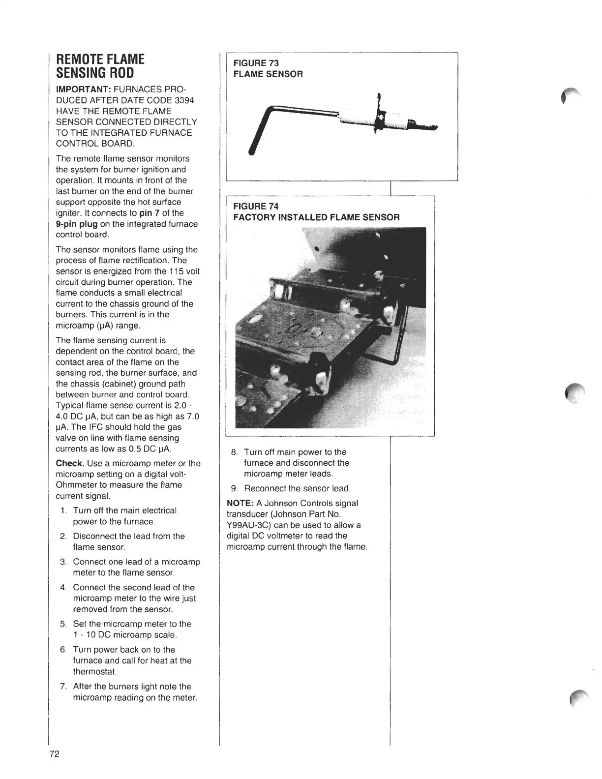
FIGURE 73
FLAME SENSOR
FIGURE 74
FACTORY INSTALLED FLAME SENSOR
8. Turn off main power to the
furnace and disconnect the
microamp meter leads.
9. Reconnect the sensor lead.
NOTE: A Johnson Controls signal
transducer (Johnson Part No.
Y99AU-3C) can be used to allow a
digital DC voltmeter to read the
microamp current through the flame.
72