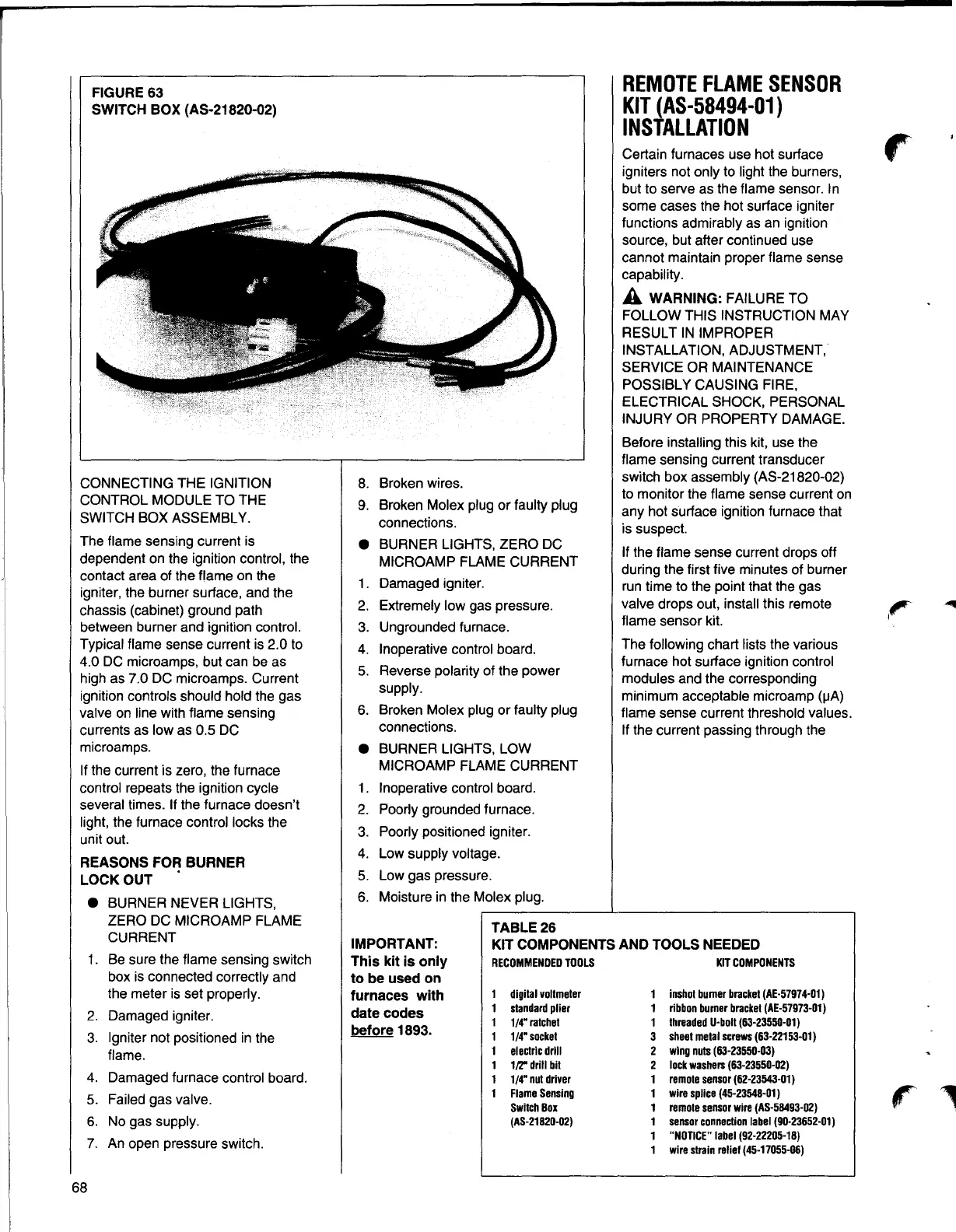
FIGURE 63
SWITCH BOX (AS-21820-02)
CONNECTING THE IGNITION
CONTROL MODULE TO THE
SWITCH BOX ASSEMBLY.
The flame sensing current is
dependent on the ignition control, the
contact area of the flame on the
igniter, the burner surface, and the
chassis (cabinet) ground path
between burner and ignition control.
Typical flame sense current is 2.0 to
4.0 DC microamps, but can be as
high as 7.0 DC microamps. Current
ignition controls should hold the gas
valve on line with flame sensing
currents as low as 0.5 DC
microamps.
If the current is zero, the furnace
control repeats the ignition cycle
several times. If the furnace doesn't
light, the furnace control locks the
unit out.
REASONS FOR BURNER
LOCKOUT •
e BURNER NEVER LIGHTS,
ZERO DC MICROAMP FLAME
CURRENT
1. Be sure the flame sensing switch
box is connected correctly and
the meter is set properly.
2. Damaged igniter.
3. Igniter not positioned in the
flame.
4. Damaged furnace control board.
5. Failed gas valve.
6. No gas supply.
7. An open pressure switch.
8. Broken wires.
9. Broken Molex plug or faulty plug
connections.
e BURNER LIGHTS, ZERO DC
MICROAMP FLAME CURRENT
1. Damaged igniter.
2. Extremely low gas pressure.
3. Ungrounded furnace.
4. Inoperative control board.
5. Reverse polarity of the power
supply.
6. Broken Molex plug or faulty plug
connections.
e BURNER LIGHTS, LOW
MICROAMP FLAME CURRENT
1. Inoperative control board.
2. Poorly grounded furnace.
3. Poorly positioned igniter.
4. Low supply voltage.
5. Low gas pressure.
6. Moisture in the Molex plug.
TABLE26
REMOTEFLAMESENSOR
KIT (AS-58494-01)
INSTALLATION
Certain furnaces use hot surface
r
igniters not only to light the burners,
but to serve as the flame sensor. In
some cases the hot surface igniter
functions admirably as an ignition
source, but after continued use
cannot maintain proper flame sense
capability.
A WARNING: FAILURE TO
FOLLOW THIS INSTRUCTION MAY
RESULT IN IMPROPER
INSTALLATION, ADJUSTMENT,
SERVICE OR MAINTENANCE
POSSIBLY CAUSING FIRE,
ELECTRICAL SHOCK, PERSONAL
INJURY OR PROPERTY DAMAGE.
Before installing this kit, use the
flame sensing current transducer
switch box assembly (AS-21820-02)
to monitor the flame sense current on
any hot surface ignition furnace that
is suspect.
If the flame sense current drops off
during the first five minutes of burner
run time to the point that the gas
valve drops out, install this remote
flame sensor kit.
The following chart lists the various
furnace hot surface ignition control
modules and the corresponding
minimum acceptable microamp (µA)
flame sense current threshold values.
If the current passing through the
IMPORTANT:
KIT COMPONENTS AND TOOLS NEEDED
This kit is only
to be used on
furnaces with
date codes
before 1893.
KIT COMPONENTS
1 inshot burner bracket (AE-57974-01)
1 ribbon burner bracket (AE-57973-01)
1 threadedU-bolt (63-23550-01)
3 sheet metal screws (63-22153-01)
2 wing nuts (63-23550-03)
2 lock washers (63-23550-02)
1 remotesensor(62-23543-01)
1 wire splice (45-23548-01)
1 remotesensorwire (AS-58493-02)
1 sensorconnectionlabel (90-23652-01)
1 "NOTICE"label (92-22205-18)
1 wire strain relief (45-17055-06)
RECOMMENDEDTOOLS
digitalvoltmeter
standardplier
1/4"ratchet
1/4" socket
electricdrill
1/r drill bit
1/4"
nutdriver
FlameSensing
Switch Box
(AS-21820-02)
68