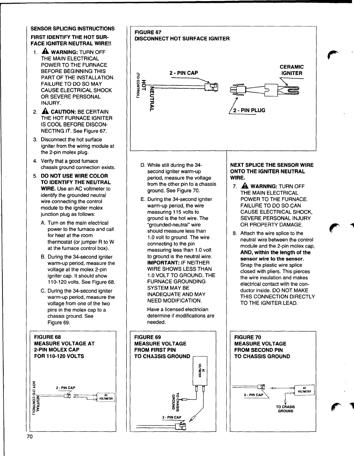
FIGURE67
DISCONNECT HOT SURFACE IGNITER
SENSOR SPLICING INSTRUCTIONS
FIRST IDENTIFY THE HOT SUR-
FACE IGNITER NEUTRAL WIRE!!
1.
A WARNING: TURN OFF
THE MAIN ELECTRICAL
POWER TO THE FURNACE
BEFORE BEGINNING THIS
PART OF THE INSTALLATION.
FAILURE TO DO SO MAY
CAUSE ELECTRICAL SHOCK
OR SEVERE PERSONAL
INJURY.
2.
A CAUTION: BE CERTAIN
THE HOT FURNACE IGNITER
IS COOL BEFORE DISCON-
NECTING IT. See Figure 67.
3. Disconnect the hot surface
igniter from the wiring module at
the 2-pin molex plug.
4. Verify that a good furnace
chassis ground connection exists.
5. DO NOT USE WIRE COLOR
TO IDENTIFY THE NEUTRAL
WIRE. Use an AC voltmeter to
identify the grounded neutral
wire connecting the control
module to the igniter molex
junction plug as follows:
A. Turn on the main electrical
power to the furnace and call
for heat at the room
thermostat (or jumper R to W
at the furnace control box).
B. During the 34-second igniter
warm-up period, measure the
voltage at the molex 2-pin
igniter cap. It should show
110-120 volts. See Figure 68.
C. During the 34-second igniter
warm-up period, measure the
voltage from one of the two
pins in the molex cap to a
chassis ground. See
Figure 69.
CERAMIC
2- PIN CAP
IGNITER
a
n :::C
~o
:ii-t z
~
o m
~
.c C:
~
l>
r
i-PINPLUG
D. While still during the 34- NEXT SPLICE THE SENSOR WIRE
second igniter warm-up ONTO THE IGNITER NEUTRAL
period, measure the voltage
WIRE.
from the other pin to a chassis
7.
A WARNING: TURN OFF
ground. See Figure 70.
THE MAIN ELECTRICAL
E. During the 34-second igniter
POWER TO THE FURNACE.
warm-up period, the wire FAILURE TO DO SO CAN
measuring 115 volts to CAUSE ELECTRICAL SHOCK,
ground is the hot wire. The
SEVERE PERSONAL INJURY
"grounded-neutral" wire OR PROPERTY DAMAGE.
should measure less than
8. Attach the wire splice to the
1.0 volt to ground. The wire
neutral wire between the control
connecting to the pin
module and the 2-pin molex cap,
measuring less than 1.0 volt
AND, within the length of the
to ground is the neutral wire.
sensor wire to the sensor.
IMPORTANT: IF NEITHER
Snap the plastic wire splice
WIRE SHOWS LESS THAN
closed with pliers. This pierces
1.0 VOLT TO GROUND, THE
the wire insulation and makes
FURNACE GROUNDING
electrical contact with the con-
SYSTEM MAY BE
ductor inside. DO NOT MAKE
INADEQUATE AND MAY
THIS CONNECTION DIRECTLY
NEED MODIFICATION.
TO THE IGNITER LEAD.
Have a licensed electrician
determine if modifications are
needed.
FIGURE68
MEASURE VOLTAGE AT
2-PIN MOLEX CAP
FOR 110-120 VOLTS
FIGURE69
MEASURE VOLTAGE
FROM FIRST PIN
TO CHASSIS GROUND .--
FIGURE 70
MEASURE VOLTAGE
FROM SECOND PIN
TO CHASSIS GROUND
\_
====C39~c
2-PIN CAP'-.
VOLTMErER
TOCHASIS
GROUND
r
2-PIN CAP
70