NOTE:Some thermostats, such as
the Honeywell T8600, have a current
flow through the
W circuitry to
operate the thermostat. During the off
cycle this small load causes UTEC
830 and 831 furnace control boards
to try to start the furnace. Since the
load is so
weak,once the induced
draft blower starts, the draw on the
W circuit drops. However, this
causes the induced draft blower
motor to start and stop erratically.
Installing the 100 ohm, 10 watt
resistor from terminals "W" and
"C" solves this problem also.
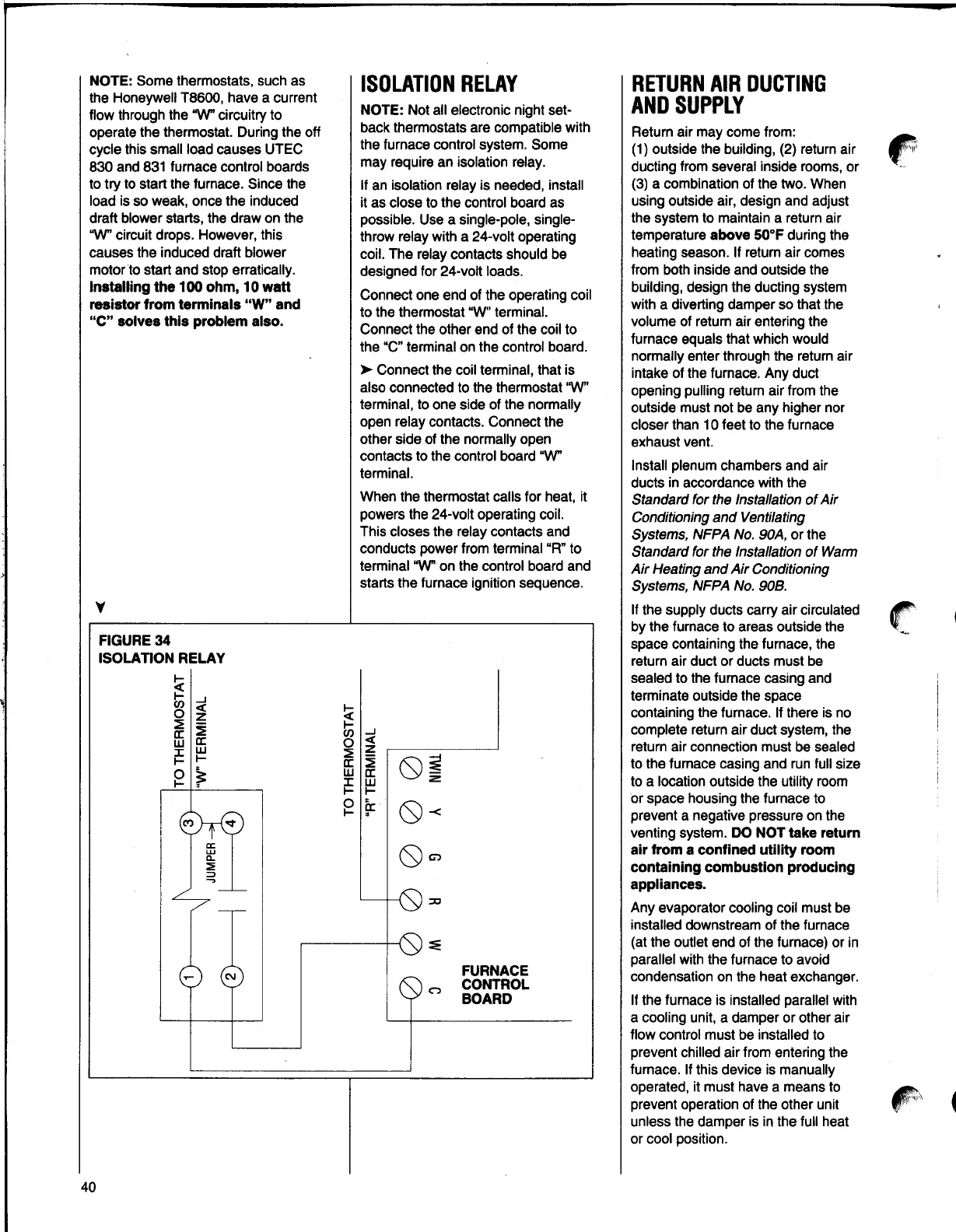
ISOLATIONRELAY
NOTE:Not all electronic night set-
back thermostats are compatible with
the furnace control system. Some
may require an isolation relay.
If an isolation relay is needed, install
it as close to the control board as
possible. Use a single-pole, single-
throw relay with a 24-volt operating
coil. The relay contacts should be
designed for 24-volt loads.
Connect one end of the operating coil
to the thermostat "W" terminal.
Connect the other end of the coil to
the "C" terminal on the control board.
►
Connect the coil terminal, that is
also connected to the thermostat
'W'
terminal, to one side of the normally
open relay contacts. Connect the
other side of the normally open
contacts to the control board
W
terminal.
When the thermostat calls for heat, it
powers the 24-volt operating coil.
This closes the relay contacts and
conducts power from terminal "R" to
terminal
W on the control board and
starts the furnace ignition sequence.
y
FIGURE34
ISOLATION RELAY
~
J
0
~
::? :E
a: a:
w w
i!: I-
~
~
I-
~
Cl)
0
::?
a:
w
J:
I-
0
I-
J
<(
z
:E
a:
w
I-
a:
.
0i
0
-<
cc
w
c..
::!:
=>
-,
0 C,
:::0
~
C\I
C")
FURNACE
CONTROL
BOARD
RETURNAIR DUCTING
AND SUPPLY
Return air may come from:
(1) outside the building, (2) return air
ducting from several inside rooms, or
(3) a combination of the two. When
using outside air, design and adjust
the system to maintain a return air
temperature
above 50°F during the
heating season. If return air comes
from both inside and outside the
building, design the ducting system
with a diverting damper so that the
volume of return air entering the
furnace equals that which would
normally enter through the return air
intake of the furnace. Any duct
opening pulling return air from the
outside must not be any higher nor
closer than 10 feet to the furnace
exhaust vent.
Install plenum chambers and air
ducts in accordance with the
Standard for the Installation of Air
Conditioning and Ventilating
Systems, NFPA No. 90A, or the
Standard for the Installation of Warm
Air Heating and Air Conditioning
Systems, NFPA No. 908.
If the supply ducts carry air circulated
by the furnace to areas outside the
space containing the furnace, the
return air duct or ducts must be
sealed to the furnace casing and
terminate outside the space
containing the furnace. If there is no
complete return air duct system, the
return air connection must be sealed
to the furnace casing and run full size
to a location outside the utility room
or space housing the furnace to
prevent a negative pressure on the
venting system.
DO NOT take return
air from a confined utility room
containing combustion producing
appliances.
Any evaporator cooling coil must be
installed downstream of the furnace
(at the outlet end of the furnace) or in
parallel with the furnace to avoid
condensation on the heat exchanger.
If the furnace is installed parallel with
a cooling unit, a damper or other air
flow control must be installed to
prevent chilled air from entering the
furnace. If this device is manually
operated, it must have a means to
prevent operation of the other unit
unless the damper is in the full heat
or cool position.
40
 Loading...