•
•
•
ELECTRICALWIRING
A WARNING: TURN OFF
FURNACE ELECTRIC POWER AT
THE FUSE BOX OR SERVICE
PANEL BEFORE MAKING ANY
ELECTRICAL CONNECTIONS.
PERMANENTLY GROUND THE
CABINET AT THE GROUNDING
CONNECTION PROVIDED IN THE
ELECTRICAL JUNCTION BOX.
COMPLETE THE GROUND
CONNECTION BEFORE MAKING
LINE VOLTAGE CONNECTIONS.
FAILURE TO USE PROPER CARE
WHEN MAKING ELECTRICAL
CONNECTIONS CAN CAUSE
PERSONALINJURY,PROPERTY
DAMAGE OR DEATH.
ELECTRICAL CONNECTIONS
The electrical supply requirements
are listed on the furnace rating plate.
Use a separate fused branch
electrical circuit containing a properly
sized fuse or circuit breaker. Run this
circuit directly from the main switch
box to an electrical disconnect switch
that must be readily accessible from
the furnace. Connect the black and
white wires from the furnace
disconnect to the junction box on the
left of the furnace. This junction box
and its internal wiring may be field
relocated to the right side of the
furnace for convenience. For proper
connection, refer to the appropriate
wiring diagram located on the inside
cover of the furnace and at the back
of this manual.
Note:L1 (hot) and L2 (neutral)
polarity must be observed when
making field electrical connections to
furnaces with hot surface ignition.
The integrated control does not
sense flame if L 1 and L2 are
reversed.
Installation of the electric supply line
should be in accordance with the
National Electric Code ANSI/NFPA
No. 70, latest edition, or Canadian
Electrical Code Part 1 - CSA
Standard C22. 1 and the local
building codes.
These codes can be obtained from:
National Fire Protection Association
Batterymarch Park
Quincy, MA 02269
Canadian Standards Association
178 Rexdale Boulevard
Etobicoke, Ontario
CANADA M9W 1 R3
THERMOSTAT 3. near concealed hot or cold water
pipes or ducts,
k-
I'
Install the room thermostat according
to the manufacturer's instructions.
Run the thermostat leads into the
blower compartment. Connect them
as shown on the wiring diagrams.
NOTE: Thermostat wire must be #18
AWG or larger. (See Table 22 below.)
TABLE 22
LOW VOLTAGE WIRING
SOLIDCOPPERWIRE• AWG
3.0 16
14 12 10
10
10
!.i:"'
16 14 12
12 10
i-!ri 2.5
10
~c
18 16 14
12 12
10::E, 2.0
icCI
... c
:CCI
50
100 150 200 250 300
......
LENGTH OF RUN • FEET <D
<D
The total wire length is the distance from the
furnaceto the thermostat and back to the
furnace.
NOTE:Do not use 24 volt control wiring smaller
than No. 18.
IMPORTANT: ALWAYS DISCON-
NECT MAIN 115 VOLT POWER
WHEN CONNECTING THERMO-
STAT WIRES. The common side of
the 24-volt transformer is grounded
to the furnace cabinet. If a low
voltage wire shorts to the cabinet or
other grounded component, damage
to the control transformer or solid
state control board may result.
Never install a thermostat:
1. on an outside wall,
2. where it may be influenced by
drafts,
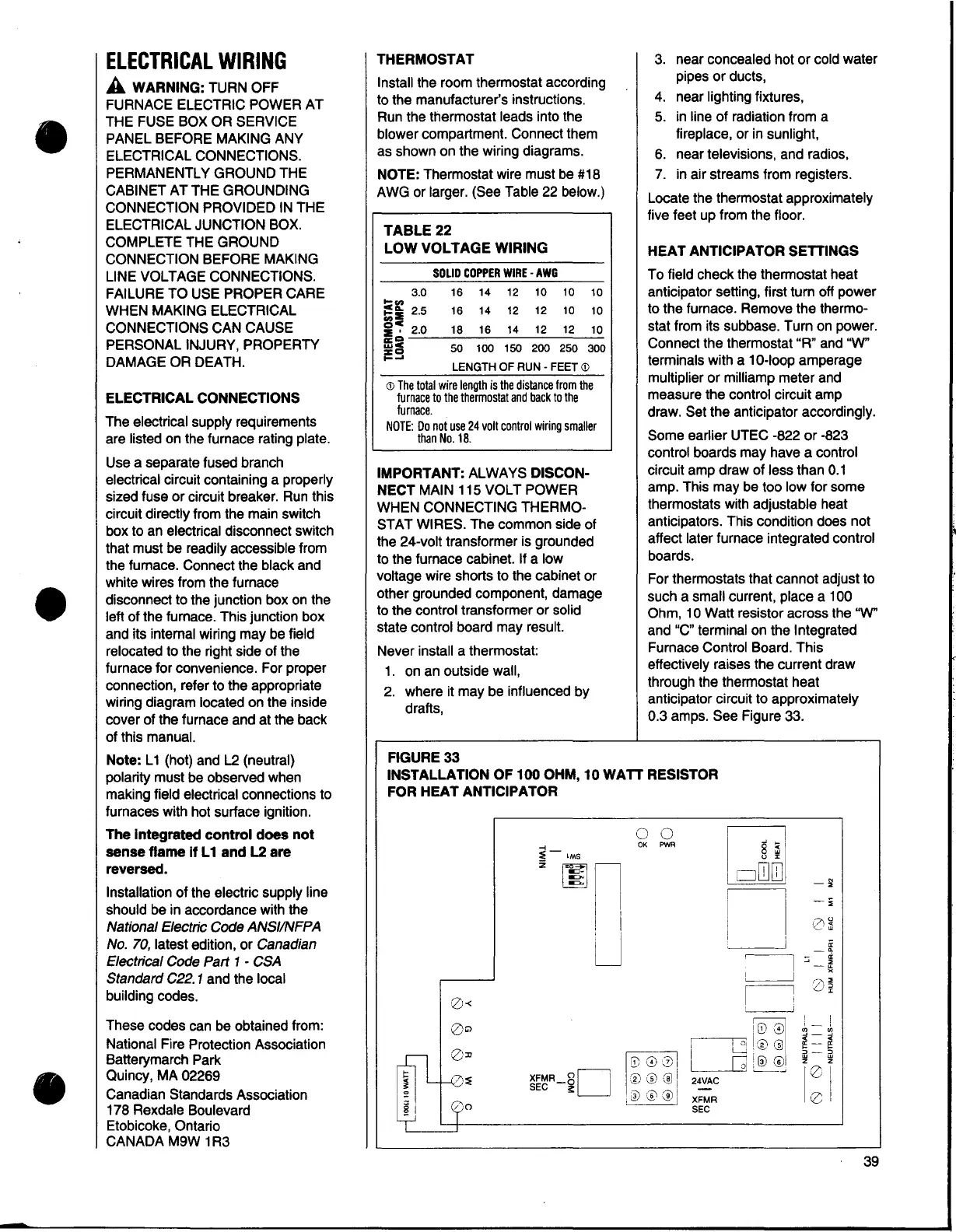
FIGURE33
4. near lighting fixtures,
5. in line of radiation from a
fireplace, or in sunlight,
6. near televisions, and radios,
7. in air streams from registers.
Locate the thermostat approximately
five feet up from the floor.
HEAT ANTICIPATOR SETTINGS
To field check the thermostat heat
anticipator setting, first tum off power
to the furnace. Remove the thermo-
stat from its subbase. Turn on power.
Connect the thermostat "R" and "W"
terminals with a 10-loop amperage
multiplier or milliamp meter and
measure the control circuit amp
draw. Set the anticipator accordingly.
Some earlier UTEC -822 or -823
control boards may have a control
circuit amp draw of less than 0.1
amp. This may be too low for some
thermostats with adjustable heat
anticipators. This condition does not
affect later furnace integrated control
boards.
For thermostats that cannot adjust to
such a small current, place a 100
Ohm, 1
OWatt resistor across the "W"
and "C" terminal on the Integrated
Furnace Control Board. This
effectively raises the current draw
through the thermostat heat
anticipator circuit to approximately
0.3 amps. See Figure 33.
INSTALLATION OF 100 OHM, 10 WATT RESISTOR
FOR HEAT ANTICIPATOR
0 0
OK PWR
8
~
u :c
□
ITlITJ
-;
n
-;;
7\ u
i<~'
~
I
-
r~
::;
-
I I
I
I
2)
I
I
I
1[i)01
,_
"'
I 01 Ir,,@
;;i_-
I
~ --
w :'v i
:>-
□
'®~
w
z
24VAC
I~
-
XFMR
SEC
39
I