~
UTEC 1012-920/920A, 1028-927 and
-928 IFC BOARD TWINNING
INSTRUCTIONS
1. Single Stage Operation
a.
Ensure that both furnace 24
volt power supplies are in
phase.
b.
Connect furnace "ONE"
control board to the
thermostat.
C.
Connect the "C", "W", and
"TWIN" terminals on one
control to the "C", "W", and
"TWIN" terminals of the
second control respectively.
d.
Set DIP switch "3" to the
"TWIN" position on both
control boards.
e.
Set both furnace control
board DIP switches #4 to
FIGURE 38
UTEC SINGLE STAGE
TWINNING
..
0
z
..
CJ)
C
. ,.._o
-
..-
I
-
the "1st" position.
I.
Set the thermostat heat
anticipator for 0.2 amps.
See Figure 118, page 108.
2. Two Stage Operation
a.
Ensure that both furnace 24
volt power supplies are in
phase.
b.
Connect furnace "ONE"
control board terminal "W" to
the "W1" terminal on the
thermostat.
C.
Connect furnace 'TWO"
control board terminal "W" to
the "W2" terminal on the
thermostat.
d. Connect control board
terminals "C" to "C" and
'TWIN" to "TWIN."
e.
Set DIP switch "3" to the
"ON" position on both
furnace control boards.
f. Set furnace control board
DIP switch #4 to the "1st"
position on furnace "ONE".
g. Set furnace control board
DIP switch #4 to the "2nd"
position on furnace "TWO".
h. Set the thermostat heat
anticipator for 0.1 amps on
each stage of heat.
See Figure 119, page 109.
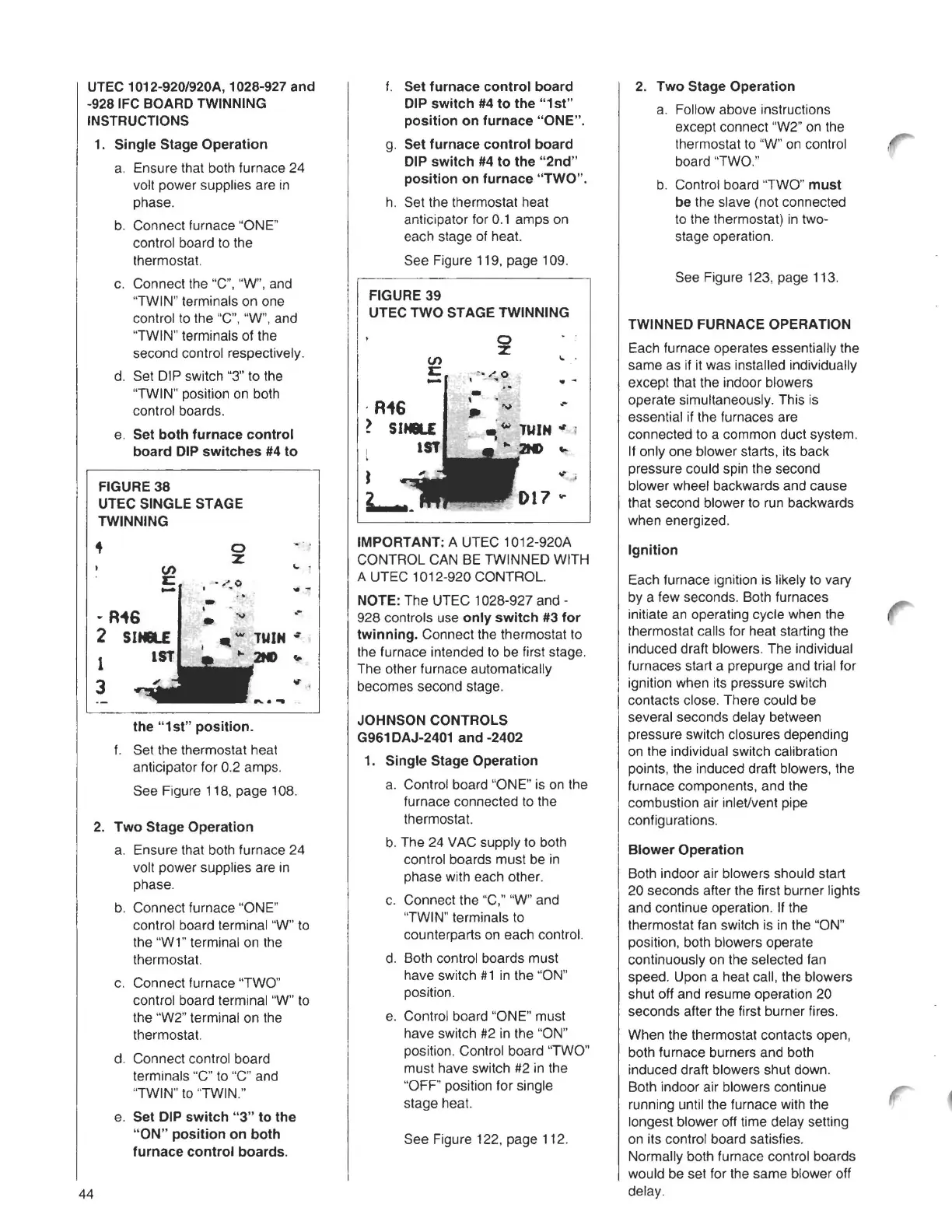
FIGURE 39
UTEC TWO STAGE TWINNING
0
z
...
U)
C
-
.-
IMPORTANT: A UTEC 1012-920A
CONTROL CAN BE TWINNED WITH
A UTEC 1012-920 CONTROL.
NOTE: The UTEC 1028-927 and -
928 controls use
only switch #3 for
twinning.
Connect the thermostat to
the furnace intended to be first stage.
The other furnace automatically
becomes second stage.
JOHNSON CONTROLS
G961 DAJ-2401 and -2402
1. Single Stage Operation
a. Control board "ONE" is on the
furnace connected to the
thermostat.
b. The 24 VAC supply to both
control boards must be in
phase with each other.
c. Connect the "C," "W" and
"TWIN" terminals to
counterparts on each control.
d. Both control boards must
have switch #1 in the ''ON"
position.
e. Control board "ONE" must
have switch #2 in the "ON"
position. Control board "TWO"
must have switch #2 in the
"OFF' position for single
stage heat.
See Figure 122, page 112.
2. Two Stage Operation
a. Follow above instructions
except connect "W2" on the
thermostat to "W" on control
board "TWO."
b. Control board "TWO"
must
be
the slave (not connected
to the thermostat) in two-
stage operation.
See Figure 123, page 113.
TWINNED FURNACE OPERATION
Each furnace operates essentially the
same as if it was installed individually
except that the indoor blowers
operate simultaneously. This is
essential if the furnaces are
connected to a common duct system.
If only one blower starts, its back
pressure could spin the second
blower wheel backwards and cause
that second blower to run backwards
when energized.
Ignition
Each furnace ignition is likely to vary
by a few seconds. Both furnaces
initiate an operating cycle when the
thermostat calls for heat starting the
induced draft blowers. The individual
furnaces start a prepurge and trial for
ignition when its pressure switch
contacts close. There could be
several seconds delay between
pressure switch closures depending
on the individual switch calibration
points, the induced draft blowers, the
furnace components, and the
combustion air inleVvent pipe
configurations.
Blower Operation
Both indoor air blowers should start
20 seconds after the first burner lights
and continue operation. If the
thermostat fan switch is in the "ON"
position, both blowers operate
continuously on the selected fan
speed. Upon a heat call, the blowers
shut off and resume operation 20
seconds after the first burner fires.
When the thermostat contacts open,
both furnace burners and both
induced draft blowers shut down.
Both indoor air blowers continue
running until the furnace with the
longest blower off time delay setting
on its control board satisfies.
Normally both furnace control boards
would be set for the same blower off
delay.
44