REMOTE FLAME SENSOR
4.
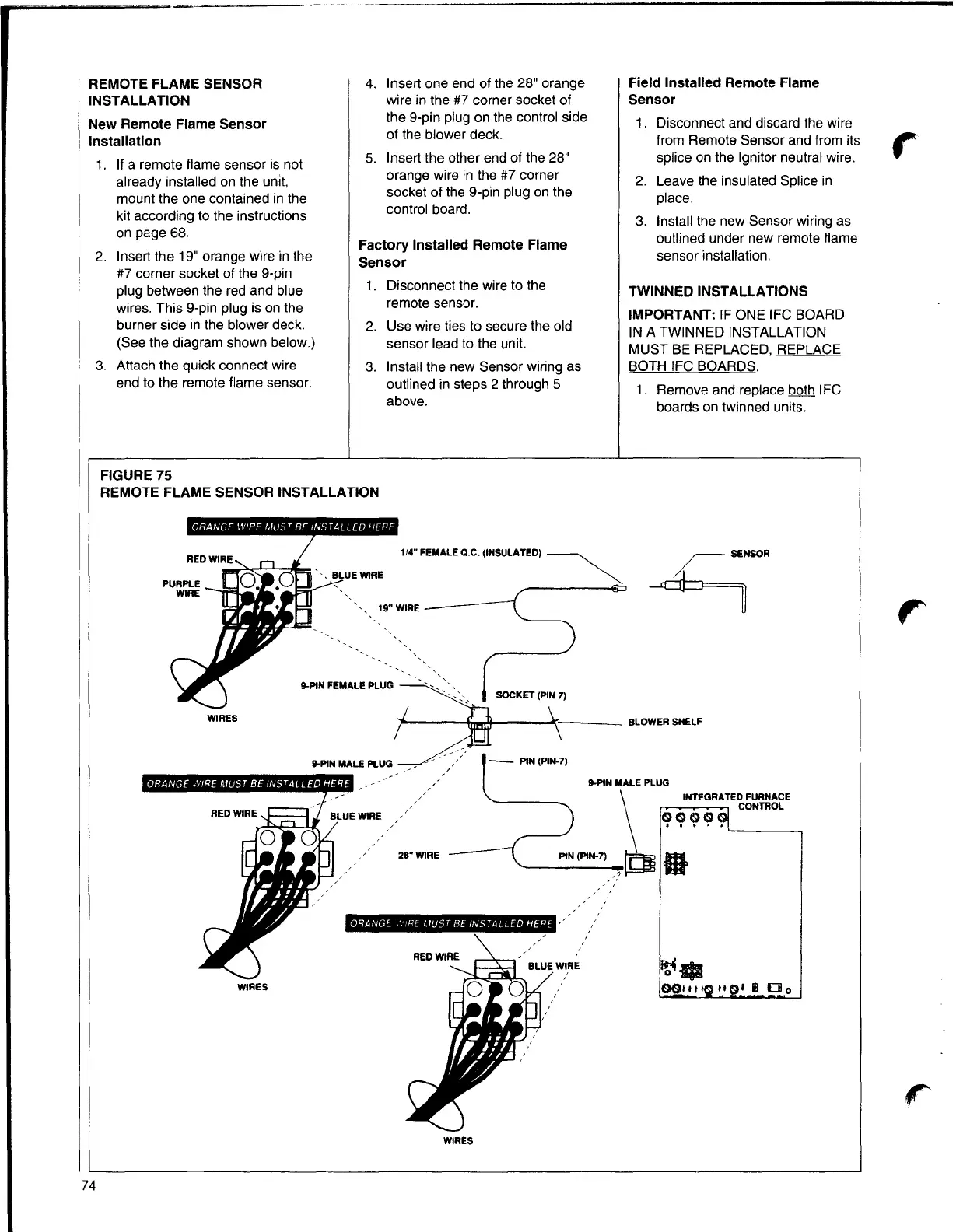
Insert one end of the 28" orange
Field Installed Remote Flame
INSTALLATION
wire in the #7 corner socket of
Sensor
the 9-pin plug on the control side
New Remote Flame Sensor
1.
Disconnect and discard the wire
of the blower deck.
Installation
from Remote Sensor and from its
r
5.
Insert the other end of the 28"
splice on the lgnitor neutral wire.
1. If a remote flame sensor is not
orange wire in the #7 corner
already installed on the unit,
2. Leave the insulated Splice in
socket of the 9-pin plug on the
mount the one contained in the
place.
control board.
kit according to the instructions
3. Install the new Sensor wiring as
on page 68.
outlined under new remote flame
Factory Installed Remote Flame
2.
Insert the 19" orange wire in the
sensor installation.
Sensor
#7 corner socket of the 9-pin
1. Disconnect the wire to the
plug between the red and blue
TWINNED INSTALLATIONS
wires. This 9-pin plug is on the
remote sensor.
IMPORTANT: IF ONE IFC BOARD
burner side in the blower deck.
2.
Use wire ties to secure the old
IN A TWINNED INSTALLATION
(See the diagram shown below.)
sensor lead to the unit.
MUST BE REPLACED, REPLACE
3. Attach the quick connect wire
3. Install the new Sensor wiring as
BOTH IFC BOARDS.
end to the remote flame sensor.
outlined in steps 2 through 5
1. Remove and replace both IFC
above.
boards on twinned units.
FIGURE 75
REMOTE FLAME SENSOR INSTALLATION
1/4" FEMALE Q.C. (INSULATED)
~
19"WIRE
9-PIN FEMALE PLUG
WIRES
9-PIN MALE PLUG
9-PIN MALE PLUG
28" WIRE
\
INTEGRATED FURNACE
CONTROL
q(?Cjl~.
'----~
PIN (PIN-7) O
~
Ill
ORANGE .'.'!RE l.1UST BE INSTALLED HERE
~-WIRES
0011 11 II I Ill
□
o
WIRES
r
74