SEQUENCE OF OPERATION
► Honeywell, JCI or UTEC
Integrated control with electronic
ignition
1. Each time the thermostat
contacts close the induced draft
blower runs for a 30-second
prepurge cycle.
2. The air proving negative
pressure switch closes.
3. After the 30 second prepurge,
EITHER the hot surface igniter
heats for 30 seconds to full
temperature, OR the direct spark
ignition electrodes spark.
4.
►
EITHER after the 30 second
hot surface igniter warm up, OR
when the electrodes begin
sparking, the gas valve opens for
an 8 - second trial for ignition.
5. The igniter lights the gas
burners. The igniter remains
energized for 7 seconds. During
the eighth second the control
checks for the presence of flame.
If flame is not sensed, the
system tries for a second
ignition. If this attempt fails the
control goes into a "self-healing"
mode for three minutes. It then
tries for ignition up to two times
more. If flame is not sensed, it
enters a one-hour soft lock out.
6. The main blower starts 22
seconds after the gas valve
opens.
FIGURE 36
ELECTRONIC IGNITION
GAS VALVE
7. When the thermostat cycle ends,
the gas valve closes, the burners
go out, the induced draft fan
stops and the negative pressure
switch opens.
8. The main blower continues until
timed off by the settings on the
integrated furnace control board.
FURNACETWINNING
A maximum of two furnaces may be
installed side by side on a common
duct system and operate as one, or
as first stage and second stage. The
twinning procedure makes both
furnace blowers operate together,
whether one or both furnaces are
firing. One thermostat can control
both units. This is necessary if the
two furnaces supply air for one 7-1/2
or 1
Oton single stage cooling
system.
To twin two furnaces, follow these
instructions and the twinning wiring
diagrams at the end of the service
manual.
IMPORTANT: ONLY TWIN
FURNACES WITH IDENTICAL
CONTROLS FROM THE SAME
MANUFACTURER OF CONTROL
BOARD.
NOTE: The "OK" LED flashes if the
twinning is not installed properly.
NOTE: Transformers of both
furnaces must be in phase.
HONEYWELL S9201 E2001 IFC
BOARD TWINNING INSTRUCTIONS
1. Single Stage Operation
a. Connect furnace "ONE" IFC
to the thermostat.
b. Remove the metal jumper
from the "XMIT" and "RCV"
terminals.
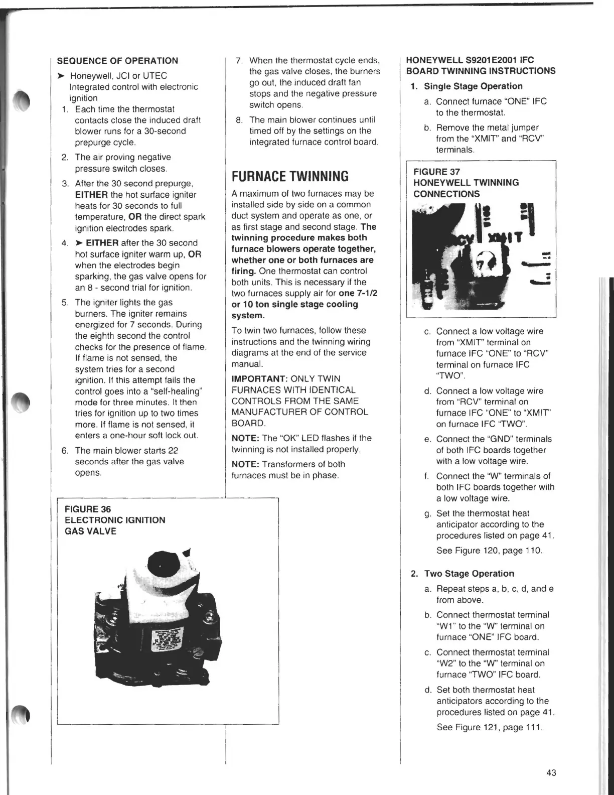
FIGURE 37
HONEYWELL TWINNING
CONNECTIONS
-
-·
C.
Connect a low voltage wire
from "XMIT" terminal on
furnace IFC "ONE" to "RCV"
terminal on furnace IFC
"TWO".
d. Connect a low voltage wire
from "RCV" terminal on
furnace IFC "ONE" to "XMIT"
on furnace IFC "TWO".
e. Connect the "GND" terminals
of both IFC boards together
with a low voltage wire.
t. Connect the "W" terminals of
both IFC boards together with
a low voltage wire.
g.
Set the thermostat heat
anticipator according to the
procedures listed on page 41 .
See Figure 120, page 110.
2. Two Stage Operation
a. Repeat steps a, b, c, d, and e
from above.
b. Connect thermostat terminal
"W1" to the
"W"terminal on
furnace "ONE" IFC board.
C. Connect thermostat terminal
"W2" to the "W" terminal on
furnace "TWO" IFC board.
d. Set both thermostat heat
anticipators according to the
procedures listed on page 41.
See Figure 121, page 111.
43