FOSSILFUELKITS
(RXPF-E01)
The Fossil Fuel Kit enables a heat
pump to be matched with a gas or oil
furnace because the indoor heat
pump coil MUST be located in the
discharge air stream leaving the gas
or oil furnace. Its most economical
application is in locations where the
heat pump provides heat at a lower
cost than gas or oil, or where the heat
pump cannot supply all the heat for
a building.
IMPORTANT: THIS FOSSIL FUEL
KIT IS USED WITH UTEC 1012-800
SERIES CONTROLS AND WITH
HONEYWELL S9201A1028 SERIES
CONTROLS.
OPERATION. The kit allows the heat
pump to operate at temperatures
(usually 30° and above) where the
heat pump is most efficient.
1. During a first stage call for heat,
the heat pump operates alone.
2. When the outdoor temperature
drops below the heat pump's
balance point, the heat pump
cannot supply all the heat
r
required. During the second
stage heat call, the Fossil Fuel
Kit stops the heat pump and the
fossil fuel furnace supplies all the
heat required.
3. During a heat pump defrost
cycle, the Fossil Fuel Kit cycles
the furnace to limit the air
temperature entering the heat
pump indoor coil.
4. During the cooling season, the
heat pump operates like a
standard cooling system.
LOCATION AND WIRING
1. Disconnect all power to both the
furnace and heat pump outdoor
unit before connecting any
wiring.
2. Install the Fossil Fuel Kit outdoor
thermostat enclosure in a
location such that at least 1
O"of
the thermostat bulb is exposed to
the outdoor air. Make low voltage
wiring connections in accordance
with the wiring diagram included
with the outdoor unit and the kit.
3. Determine the heat pump
balance point temperature and
set the outdoor thermostat at this
point or slightly below.
4. Install the Fossil Fuel Kit blower
relay enclosure in the blower
compartment of the furnace near
the furnace control box.
A. Connect one of the white
wires to the "W" terminal of
the furnace control board.
8. Connect the other white wire
to the "C" terminal of the
furnace control board.
C. Connect the yellow wire with
the eyelet to the "Y" terminal
of the furnace control board.
D. Connect the other yellow lead
to the low voltage yellow
leads from the thermostat and
the outdoor unit.
E. Disconnect the blower cooling
and heating speed wires from
the furnace control board.
TAPE OFF the heating
speed wire.
F. Connect the black jumper
wire provided with the Fossil
Fuel Kit to both the Heat and
Cool terminals on the furnace
control board (use the "Y"
connectors provided with the
Kit if necessary).
G. Reconnect the blower cooling
speed lead to the Cool
terminal of the furnace control
board.
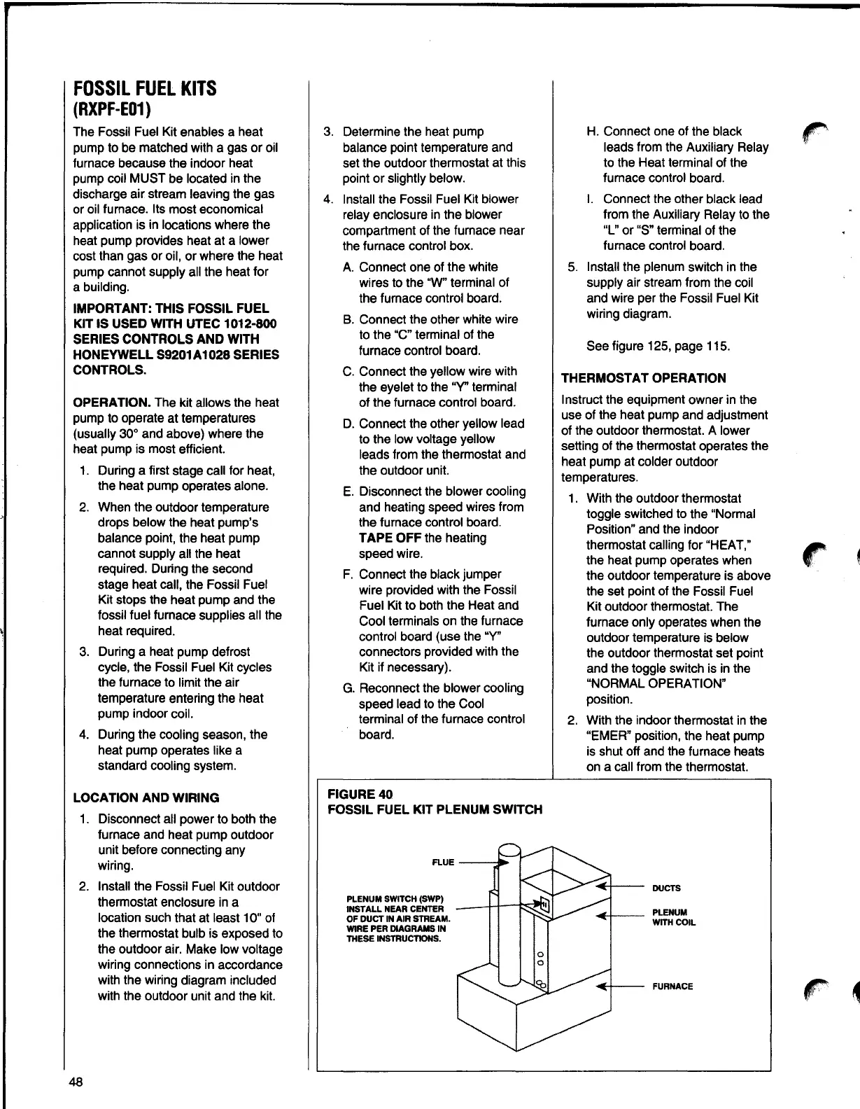
FIGURE40
FOSSIL FUEL KIT PLENUM SWITCH
PLENUM SWITCH (SWP)
INSTALL NEAR CENTER
OF DUCT IN AIR STREAM.
WIRE PER DIAGRAMS IN
THESE INSTRUCTIONS.
H. Connect one of the black
leads from the Auxiliary Relay
to the Heat terminal of the
furnace control board.
I. Connect the other black lead
from the Auxiliary Relay to the
"L" or "S" terminal of the
furnace control board.
5. Install the plenum switch in the
supply air stream from the coil
and wire per the Fossil Fuel Kit
wiring diagram.
See figure 125, page 115.
THERMOSTAT OPERATION
Instruct the equipment owner in the
use of the heat pump and adjustment
of the outdoor thermostat. A lower
setting of the thermostat operates the
heat pump at colder outdoor
temperatures.
1. With the outdoor thermostat
toggle switched to the "Normal
Position" and the indoor
thermostat calling for "HEAT,"
the heat pump operates when
the outdoor temperature is above
the set point of the Fossil Fuel
Kit outdoor thermostat. The
furnace only operates when the
outdoor temperature is below
the outdoor thermostat set point
and the toggle switch is in the
"NORMAL OPERATION"
position.
2. With the indoor thermostat in the
"EMER" position, the heat pump
is shut off and the furnace heats
on a call from the thermostat.
DUCTS
PLENUM
WITH COIL
FURNACE
48