J
flame drops below this microamp
value the control module may shut
down the furnace.
MINIMUM
ACCEPTABLE HSI FURNACE
AMPVALUES CONTROL
1.5 HONEYWELL-A1028
1.0 E2001HONEYWEL-
1.5 UTEC1012-823
1.0 UTEC1012-830
1.0 UTEC1012-831
1.0
UTEC1012-920
The remote flame sense kit consists
of the components listed in Table 26.
The tools needed to install the kit are
also listed.
The following shows the guidlines
needed to install the Remote Flame
Sensor Kit (AS-58494-01) on the Low
Profile furnace.
SENSOR MOUNTING BRACKET
IDENTIFICATION
The 34" Low Profile furnace uses
the inshot burner bracket (AE-57974-
01) with two screw holes on the side
and the larger sensor mounting
opening and screw hole in the center.
FIGURE 64
INSHOT BURNER BRACKET
SENSOR MOUNTING IN THE 34"
LOW PROFILE FURNACE
NOTE: THIS KIT IS DESIGNED
TO BE INSTALLED WITH THE
BURNERS AND GAS ASSEMBLY
IN PLACE.
Bracket Location and Mounting
1. Remove all necessary covers
and panels to gain access to the
burners.
2. The inshot burner bracket
mounts to the center of the
appropriate burner support
bracket as shown. Position the
inshot burner bracket on the
burner side of the burner support
bracket with its two screw holes
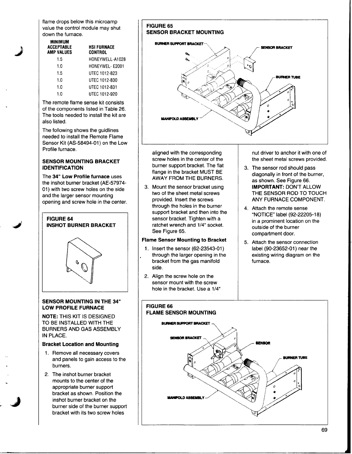
FIGURE 65
SENSOR BRACKET MOUNTING
..L SENSOR BRACKET
)':::?
~
aligned with the corresponding
screw holes in the center of the
burner support bracket. The flat
flange in the bracket MUST BE
AWAY FROM THE BURNERS.
3. Mount the sensor bracket using
two of the sheet metal screws
provided. Insert the screws
through the holes in the burner
support bracket and then into the
sensor bracket. Tighten with a
ratchet wrench and 1/4" socket.
See Figure 65.
Flame Sensor Mounting to Bracket
1. Insert the sensor (62-23543-01)
through the larger opening in the
bracket from the gas manifold
side.
2. Align the screw hole on the
sensor mount with the screw
hole in the bracket. Use a 1/4"
nut driver to anchor it with one of
the sheet metal screws provided.
3. The sensor rod should pass
diagonally in front of the burner,
as shown. See Figure 66.
IMPORTANT: DON'T ALLOW
THE SENSOR ROD TO TOUCH
ANY FURNACE COMPONENT.
4. Attach the remote sense
"NOTICE" label (92-22205-18)
in a prominent location on the
outside of the burner
compartment door.
5. Attach the sensor connection
label (90-23652-01) near the
existing wiring diagram on the
furnace.
FIGURE 66
FLAME SENSOR MOUNTING
BURNER SUPPORT BRACKET
--~::\<
IINIOR
BURNER TUBE
IIANFOLDASSEMBLY
69