MAIN POWER "J" BOX
The main power J-box is on the left
side of the furnace and must have
line power connected with proper
polarity. This is especially important
with electronic ignition furnaces.
Failure to connect the line power with
proper polarity causes the burner not
to sense ignition and shut down. After
four or five tries for ignition, the
system goes into soft lockout.
A grounding wire is provided to
connect to the incoming grounding
wire from line power. The furnace
must be permanently grounded in
accordance with all national and local
codes.
BLOWERDOORSWITCH
A blower door switch is attached to
the J-box. The switch closes by
putting the blower door in place. The
door must be properly installed to
ensure that the switch closes its
contacts. It is designed to break all
power to the furnace if the blower
door opens. The switch is in the
115-volt primary circuit.
Check. The following continuity test
can be made on the switch.
1. Turn off power and remove the
blower door.
2. Disconnect the switch leads.
3. Connect an Ohmmeter across
the switch terminals.
4. The Ohmmeter should read
infinite Ohms. If not, replace the
switch assembly.
5. Depress the switch plunger.
6. The meter should read zero
Ohms. If not, replace the switch
assembly.
FIGURE 92
BLOWER DOOR SWITCH
The condition of the blower door
switch can be checked with power on
using a volt meter. If the meter shows
voltage, the switch is open.
A zero
volt reading confirms a closed switch.
CONTROLS
The furnace uses several safety
controls, some of which are unique to
this unit. These controls monitor the
operation of the furnace and shut it
off if a malfunction occurs.
NEGATIVEPRESSURE
SWITCH
Operation. All models of the Low
Profile furnace use a negative
pressure switch. It checks for proper
operation of the induced draft blower
and a blocked vent condition. The
induced draft blower causes a
negative pressure in the inducer
housing which closes the pressure
switch contacts. The induced draft
blower must generate a negative
pressure at least 0.1" below the
switch setting. The pressure switch
y
TABLE 27
PRESSURE SWITCH SETTINGS
FURNACEINPUT
SWITCHSET MAXMK.PT.
*45,000
-0.30"
WC
0.42
50,000
-0.30"
WC
0.42
*67,500
-0.30"
WC
0.42
75,000
-0.30"
WC
0.42
100,000
-0.30"
WC 0.42
125,000
-0.35"
WC
0.47
150,000
-0.35"
WC
0.47
* Units built before
date code F4797
had a -0.1 O" setting.
contacts route power to the gas valve
in standing pilot units or communicate
with the integrated furnace control
board to start the ignition sequence
on electronic ignition units.
j
Check. Use a Magnehelic gauge to
check the operation of the negative
pressure switch.
1. Place a tee in the pressure
switch hose.
2. Connect the Magnehelic gauge
hose to the stem of the tee.
3. Run the induced draft blower.
4. Note the negative pressure on
the Magnehelic gauge. The
negative pressure must be low
enough to close the contacts.
5. Use an Ohmmeter to measure
the resistance of the switch
contacts. A zero Ohm reading
confirms a closed switch.
There are several reasons for the
pressure switch not to close.
1. An inoperative induced draft
blower.
2. A loose or leaky pressure switch
hose.
3. A blockage in the vent.
4. Severe downdrafts canceling the
draft from the inducer fan.
5. A leaky gasket at the induced
draft blower.
6. Restricted vent.
The pressure switch contacts must
open before the unit can go through
another heating cycle.
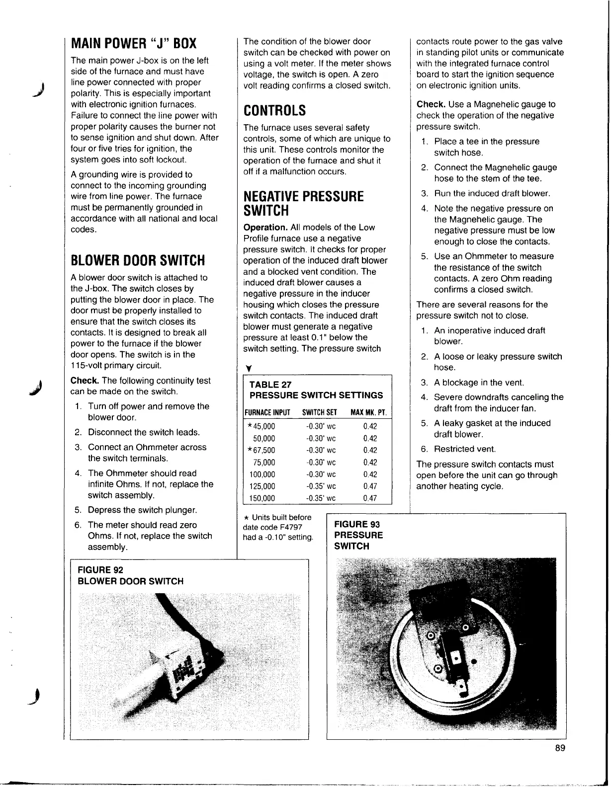
FIGURE 93
PRESSURE
SWITCH
J
89