If the supply gas line pressure is
above these ranges, install an in-line
gas regulator to the furnace for
natural gas units. With LP gas, have
the LP supplier reduce the line
pressure at the tank regulator.
If supply gas line pressure is below
these ranges, either remove any
restrictions in the gas supply piping or
enlarge the gas pipe. With LP gas,
have the LP supplier adjust the line
pressure at the tank regulator.
Manifold Gas Pressure
Measurement.
Natural gas manifold
pressure should be 3.5" w.c.
LP gas manifold pressure should be
10.0" w.c. Only small variations in
gas flow should be made by adjusting
the pressure regulator.
1. With gas to the unit shut off at
the manual gas valve, remove
the manifold pressure tap cover.
2. Connect a U-Tube manometer to
this pressure tap.
3. Turn on the gas supply and
operate the furnace.
4. Note the manifold gas pressure
on the manometer.
A. 3.5" w.c. for natural gas.
B. 10.0" w.c. for LP gas.
5. To adjust the pressure regulator,
remove the regulator cap.
6. Turn the adjustment screw
clockwise to increase pressure,
or counterclockwise to decrease
pressure.
7. Securely replace the regulator
cap.
8. Shut off the gas at the manual
gas valve and remove the
U-Tube manometer.
9. Replace the pressure tap cover
before turning on the gas.
TABLE 31
NATURAL GAS PIPE CAPACITY TABLE (CU. FTJHR.)
Capacityof gas pipe of different diameters and lengths In cu. ft. per hr. with pressure drop of 0.3 in. and specific
gravity of 0 60 (natural gas).
Nominal
Iron Pipe
Length of Pipe, Feet
Size, Inches
10 20 30 40 50
60 70
80
1/2 132 92 73 63 56 50
46 43
3/4 278 190 152 130 115 105 96 90
1
520 350 285
245 215 195 180 170
1-1/4
1,050
730 590 500
440 400 370
350
1-1/2
1,600 1,100 890
760
670
610 560
530
Alter the length of pipe has been determined, select the pipe size which will provide the minimum cubic feet per hour
requiredfor the gas input rating of the furnace. By formula:
Gas Input of Furnace (BTU/HR)
Cu. Ft Per Hr. Required
HeatingValue of Gas (BTU/FT')
The gas input of the furnace is marked on the furnace rating plate. The heating value of the gas (BTU/FT3) may be
determinedby consulting the local natural gas utility or the LP gas supplier.
LP GAS PIPE CAPACITY TABLE (1000's BTU/HR)
Maximum capacity of pipe in thousands of BTU per hour of undiluted liquefied petroleum gases (at 11 inches water
column inlet pressure).
Nominal
Length of Pipe, Feet
Iron Pipe
Size, Inches
10
20
30
40 50
60 70 80 90 100 125 150
1/2 275
189
152 129 114 103
96
89 83 78
69
63
3/4 567
393
315 267 237 217 196
182
173 162 146 132
1 1,071 732
590
504 448
409
378 346 322 307 275 252
1-1/4 2,205
1.496
1,212 1,039 913 834
771
724
677
630
567 511
1-1/2 3,307 2,299
1,858
1,559
1.417
1,275 1,181 1,086 1,023
976 866 787
2
6,221 4,331
3.465
2,992 2,646
2,394
2,205 2,047 1,921
1.811 1,606
1.496
Example (LP):
Input BTU requirement of unit. 150,000
Equivalentlength of pipe, 60 ft. = 3/4" IPS required.
LP COPPER TUBE SIZING TABLE (1000's BTU/HR)
Sizing between single or second stage (low pressure) regulator and appliance Maximum capacity of pipe in
thousandsof BTU per hour of undiluted propanegases (at 1
r w.c. setting).
Outside Diameter
Copper Tubing,
Length of Pipe, Feet
Typel 10 20
30 40 50
60 80 100 125 150
3/8"
49
34
27 23 20 19 16 14 11 10
1/2" 110
76
61
52 46 42 36
32
28 26
5/8"
206
141 114 97 86 78 67
59
52 48
3/4 348 239 192 164 146 132 113 100 89 80
7/8"
536 368 296 253
224
203 174 154
137
124
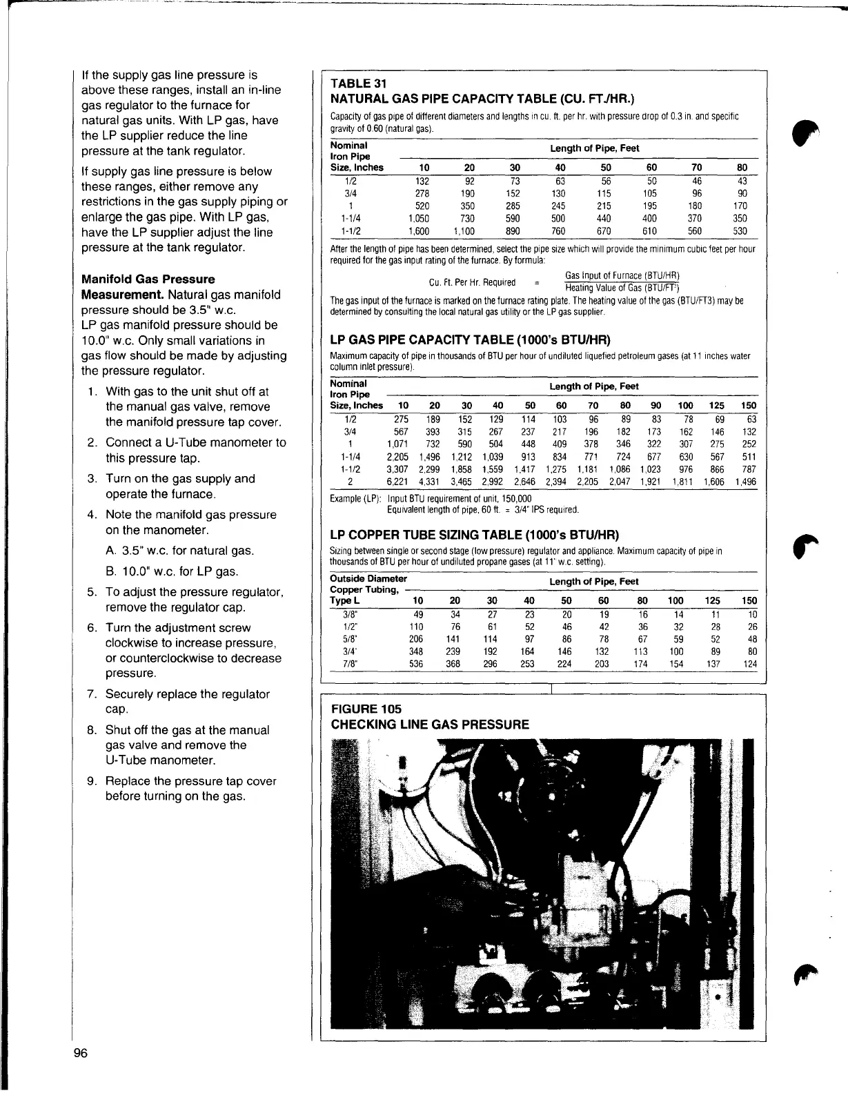
FIGURE 105
CHECKING LINE GAS PRESSURE
96