Indoor thermostat set to "EMERG".
1. A call for heat at the indoor
thermostat operates the
furnace only.
2. The heat pump is off.
Outdoor thermostat toggle switch
set
to "HEAT PUMP ONLY".
1.
A call for heat or cool at the
indoor thermostat operates the
heat pump only.
2. The indoor blower operates on
the cooling speed.
See wiring diagram Figure 126, on
page 116.
FOSSILFUELKIT (RXPF - F02)
The RXPF - F02 fossil fuel kit with
solid state control board is designed
to meet all TV A requirements and
provides for automatic 2nd stage
operation ("W2") of the gas furnace.
The furnace control board, heat pump
low voltage controls, thermostat, all
other sensors and controls connect to
the solid state control board.
LOCATION AND WIRING
Mount the F02 kit wiring board
indoors near the furnace, and F02
outdoor thermostat enclosure as with
the F01 system. Make all other wiring
connections according to its wiring
diagram. Install the rest of the system
as with the RXPF - F01 instructions.
THERMOSTAT OPERATIONS
Indoor thermostat set
to "HEAT";
outdoor thermostat toggle switch
set to "NORMAL OPERATION".
1. Call for 1st stg. heat at the indoor
thermostat.
2. The heat pump runs and the
indoor blower operates in
the cooling speed when the
outdoor temperature is above the
RXPF - F02 set point.
3. The furnace only operates when
the outdoor temperature is below
the RXPF - F02 set point. The
indoor blower does not run
during the furnace warm-up
period.
4. A call for 2nd stg. heat operates
the furnace only and lights the
Aux Ht. indicator. The heat pump
is off.
5. During defrost the plenum switch
cycles the furnace, and the
blower runs in the cooling speed
continuously.
IMPORTANT: The outdoor
temperature must be ABOVE the
RXPF - F02 set point. If not, the
furnace heats on a call for cooling.
Indoor thermostat set to "EMERG".
1 . A call for heat at the indoor
thermostat operates the
furnace only.
2. The heat pump is off.
3. The thermostat emergency heat
light is on.
Outdoor thermostat toggle switch
set to "HEAT PUMP ONLY".
1 .
A call for heat or cool at the
indoor thermostat operates the
heat pump only.
2. The indoor blower operates in
the cooling speed.
IMPORTANT: THE MANUFAC-
TURER RECOMMENDS INSTALL-
ING THE PLENUM SENSOR TO
PROVIDE COMFORT TO THE
HOMEOWNER DURING HEAT
PUMP DEFROST. HOWEVER, IF
NOT INSTALLING THE PLENUM
SENSOR, ALWAYS CONNECT
"W2" ON THE WIRING BOARD TO
THE HEAT PUMP.
See wiring diagram Figure 127, on
page 117.
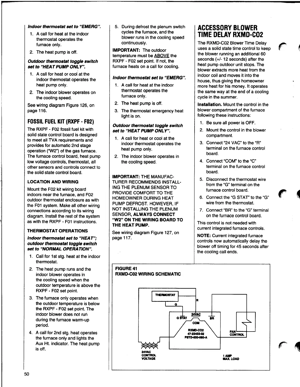
FIGURE41
RXMD-C02 WIRING SCHEMATIC
THERMOSTAT1------,
?v'v'v'\
24VAC
CONTROL
VOLTAGE
Q
ACCESSORYBLOWER
TIME DELAY RXMD-CO2
The RXMD-C02 Blower Time Delay
uses a solid state time control to keep
the blower running an additional 60
seconds(+/- 12 seconds) after the
heat pump outdoor unit stops. The
blower extracts more heat from the
indoor coil and moves it into the
house, thus giving the homeowner
more heat for his money. It operates
the same way at the end of a cooling
cycle in the summer.
Installation. Mount the control in the
blower compartment of the furnace
following these instructions:
1. Be sure all power is OFF.
2.
Mount the control in the blower
compartment.
3. Connect "24 VAC" to the "R"
terminal on the furnace control
board.
4. Connect "COM" to the "C"
terminal on the furnace control
board.
5. Disconnect the thermostat wire
from the "G" terminal on the
furnace control board.
6.
Connect the "G STAT" to the "G"
wirefrom the thermostat.
7. Connect "BR" to the "G" terminal
on the furnace control board.
This control is not needed with
current integrated furnace controls.
NOTE: Current integrated furnace
controls now automatically delay the
blower off timing for 45 seconds after
the cooling call ends.
R
1Aa'
MAX.LOAD
r
r
-
r 1
50