•
•
Ignition Failure
Each furnace is under the control of
its ignition control board. It is possible
that one furnace could be locked out
due to failure to light or failure to
sense flame. The other furnace could
operate and satisfy the thermostat.
The locked out control would then
reset during the off cycle and could
operate normally during the next heat
call. If one furnace becomes
disabled, the second furnace
continues to operate.
If a high limit control opens on either
furnace, both gas controls close and
both indoor air blowers continue to
operate. The induced draft blower
remains on in the furnace with the
open limit, and the induced draft
blower shuts off in the other furnace.
When the limit resets with the
thermostat still calling for heat, the
other furnace immediately initiates an
operating cycle. The induced draft
blower on the furnace that had the
open limit continues to run for 30
seconds, then shuts off. Both indoor
air blowers continue to operate
through the blower off delay time then
shutoff. Thefurnacethathadthe
open limit then starts its burner cycle.
Both indoor air blowers restart 20
seconds after the first burner fires.
Burner ignition on the furnace that
had the open limit could be delayed
3 to 4 minutes after the first furnace
ignites.
Install the RXGP - F03 kit when
UTEC1012-925IFC BOARD
twinning to both assure that both
TWINNINGINSTRUCTIONS
indoor blowers run simultaneously
(RXGP- F03)
and so that when either blower door
is opened, both furnaces shut down.
IMPORTANT: THIS KIT MAY
The kit contains additional blower
ONLY BE USED WITH THE
door switches, wiring connections,
FOLLOWING GAS FURNACE
and other hardware needed to twin
MODELS EQUIPPED WITH THE
the above listed furnace models.
UTEC 1012-925 IFC.
(-)GDJ SERIES
(-)GPJ SERIES
(-)GLJ SERIES
(-)GVJ SERIES
A WARNING: THESE INSTRUC-
TIONS ARE INTENDED AS AN AID
TO QUALIFIED, LICENSED
SERVICE PERSONNEL FOR
PROPER INSTALLATION, ADJUST-
MENT, AND OPERATION OF THIS
PRODUCT. READ THESE
INSTRUCTIONS THOROUGHLY
BEFORE ATTEMPTING INSTAL-
LATION OR OPERATION. FAILURE
TO FOLLOW THESE INSTRUC-
TIONS MAY RESULT IN IMPROPER
INSTALLATION, ADJUSTMENT,
SERVICE OR MAINTENANCE
POSSIBLY RESULTING IN FIRE,
ELECTRICAL SHOCK, CARBON
MONOXIDE POISONING,
EXPLOSION, PERSONAL INJURY
OR PROPERTY DAMAGE.
y
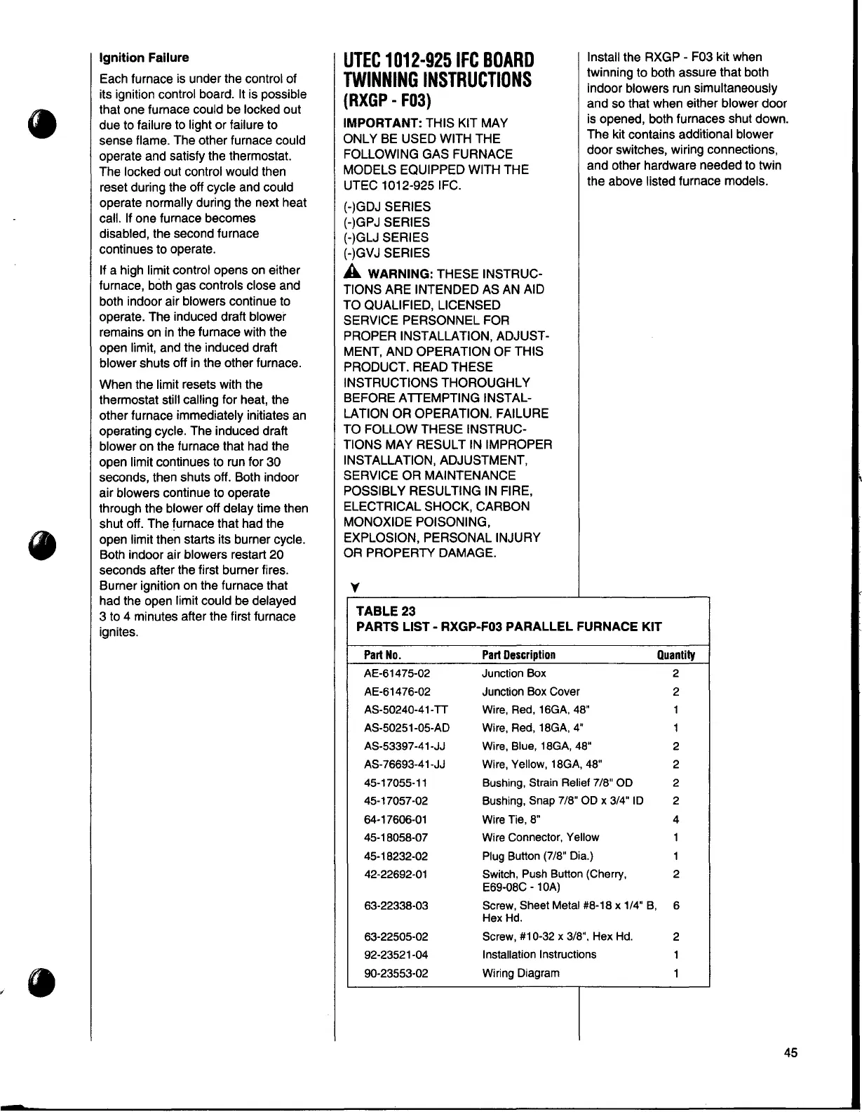
TABLE23
PARTS LIST - RXGP-F03 PARALLEL FURNACE KIT
Part No.
Part Description
Quantity
AE-61475-02 Junction Box 2
AE-61476-02 Junction Box Cover 2
AS-50240-41-TT Wire, Red, 16GA, 48" 1
AS-50251-05-AD Wire, Red, 18GA, 4"
1
AS-53397-41-JJ Wire, Blue, 18GA, 48"
2
AS-76693-41-JJ Wire, Yellow, 18GA, 48"
2
45-17055-11
Bushing, Strain Relief 7/8" OD
2
45-17057-02 Bushing, Snap 7/8" OD x 3/4" ID 2
64-17606-01 Wire Tie, 8" 4
45-18058-07 Wire Connector, Yellow 1
45-18232-02 Plug Button (7/8" Dia.) 1
42-22692-01
Switch, Push Button (Cherry, 2
E69-08C - 1 0A)
63-22338-03 Screw, Sheet Metal #8-18 x 1/4" B,
6
Hex Hd.
63-22505-02
Screw, #10-32 x 3/8". Hex Hd.
2
92-23521-04
Installation Instructions
1
90-23553-02
Wiring Diagram
1
45