this assembly. Locate the ground-
joint union in accordance with all
applicable codes.
Install a drip leg in
the gas supply line as close to the
furnace as possible. Use a pipe
compound resistant to the action of
LP gases on all threaded pipe
connections.
Install gas piping in accordance with
local codes and utility company
regulations. Consult the local gas
company for location of a manual
main valve.
The gas line should be
of adequate size to prevent undue
pressure drop and never smaller
than the pipe size to the
combination gas valve.
Use the
following table to select the pipe size
to connect the furnace.
The furnace comes shipped for gas
pipe connection to the left side of the
furnace. However, it may enter the
furnace from either side. To change
to the right side inlet bring the supply
piping in through the opening in the
right side of the cabinet. Use two
elbows to pipe the gas to the gas
valve. Be sure the ground joint union
is accessible and in place.
Do not make any attempt to derate
the furnace by changing gas orifices
or the gas pressure. Allow the natural
derate of the gas to occur. The
natural derate is approximately 1.8%
per 1 000 feet.
No orifice sizing or other derate
procedures are necessary unless the
natural gas BTU content exceeds
1075 BTU/ft
3
at sea level or the LP
gas BTU content exceeds 2500
BTU/ft
3
at sea level. If the heating
values exceed these levels, consult
the manufacturer for specific derate
procedures.
GAS SUPPLY AND PRESSURES
Natural gas supply pressure should
be 5" to 10.5" w.c. LP gas supply
pressure should be 11" to 13" w.c.
This pressure must be main-
tained with all other gas-fired
appliances in operation. Do not
exceed a maximum gas supply
pressure of 13" w.c. with any fuel.
The minimum supply pressure to the
gas valve for proper furnace input
adjustments is 5" w.c. for natural gas
and 11" w.c. for LP gas.
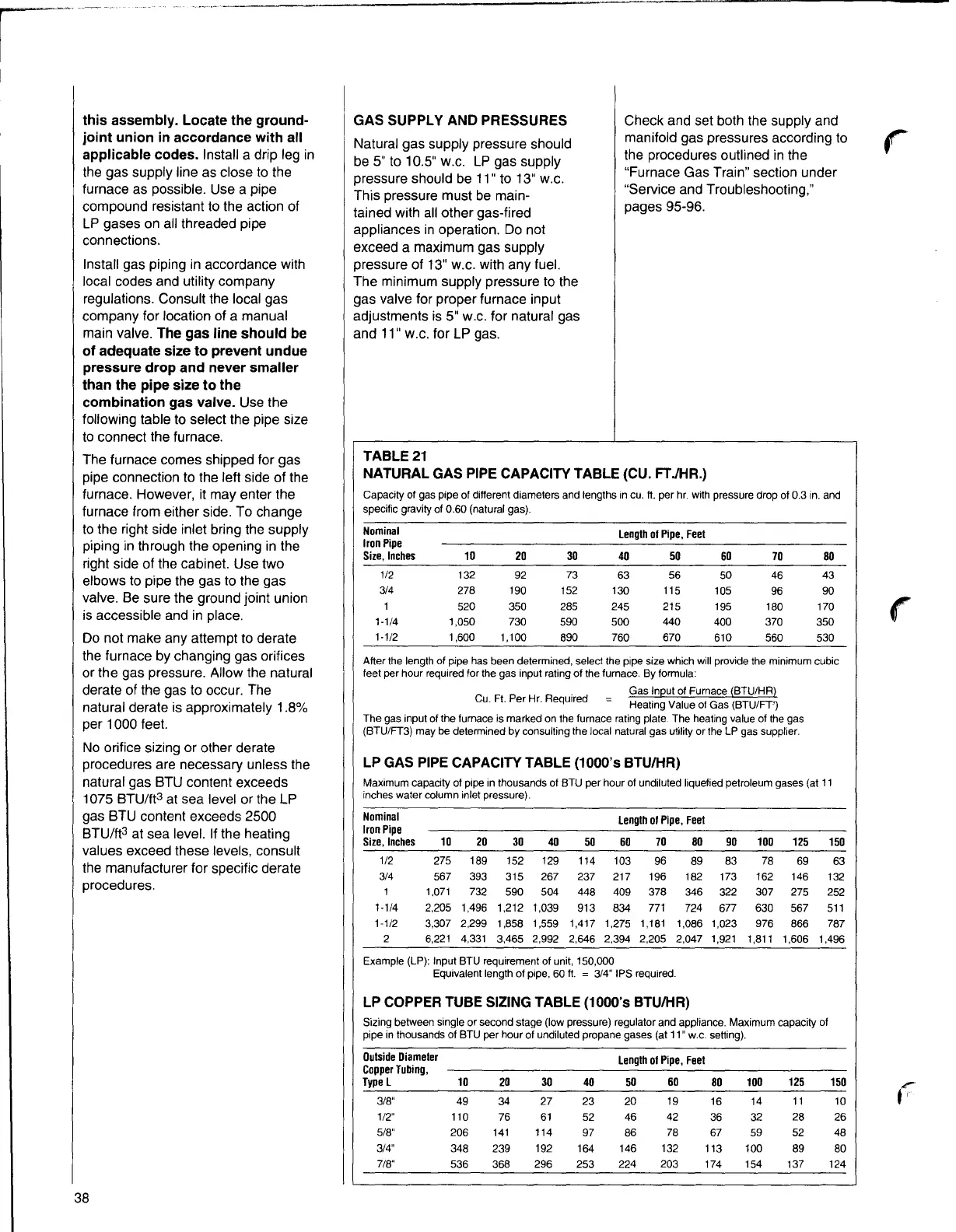
TABLE 21
Check and set both the supply and
manifold gas pressures according to
the procedures outlined in the
"Furnace Gas Train" section under
"Service and Troubleshooting,"
pages 95-96.
r
NATURAL GAS PIPE CAPACITY TABLE (CU. FT JHR.)
Capacity of gas pipe of different diameters and lengths in cu. ft. per hr. with pressure drop of 0.3 in. and
specific gravity of 0.60 (natural gas).
Nominal
Iron Pipe
Lengthof Pipe, Feet
Size, Inches
10 20 30 40 50 60
70 80
1/2
132 92
73
63
56 50 46 43
3/4 278 190
152
130 115
105
96
90
520
350
285 245 215 195 180 170
1-1/4 1,050 730
590 500
440
400 370 350
1-1/2 1,600 1,100
890 760 670
610 560 530
After the length of pipe has been determined, select the pipe size which will provide the minimum cubic
feet per hour required for the gas input rating of the furnace. By formula:
Gas Input of Furnace (BTU/HR)
Cu. Ft. Per Hr. Required
Heating Value of Gas (BTU/FT')
The gas input of the furnace is marked on the furnace rating plate. The heating value of the gas
(BTU/FT3) may be determined by consulting the local natural gas utility or the LP gas supplier.
LP GAS PIPE CAPACITY TABLE (1000's BTU/HR)
Maximum capacity of pipe in thousands of BTU per hour of undiluted liquefied petroleum gases (at 11
inches water column inlet pressure).
Nominal
Lengthol Pipe, Feet
Iron Pipe
Size, Inches
10 20 30 40
50 60
70 80 90 100 125
150
1/2 275 189 152 129
114 103 96 89 83 78 69
63
3/4 567 393 315
267 237 217 196 182
173 162
146 132
1 1,071 732
590 504 448 409 378 346 322 307 275 252
1-1/4 2,205
1,496 1,212 1,039
913 834
771 724
677 630 567 511
1-1/2
3,307 2,299 1,858 1,559 1,417 1,275 1,181 1,086 1,023 976
866
787
2 6,221
4,331
3,465 2,992 2,646 2,394 2,205 2,047 1,921
1,811 1,606 1,496
Example {LP): Input BTU requirement of unit, 150,000
Equivalent length of pipe, 60 ft.
= 3/4" IPS required.
LP COPPER TUBE SIZING TABLE (1000's BTU/HR)
Sizing between single or second stage (low pressure) regulator and appliance. Maximum capacity of
pipe in thousands of BTU per hour of undiluted propane gases (at 11" w.c. setting).
OutsideDiameter
CopperTubing,
Lengthof Pipe, Feet
Type
L
10 20 30 40 50 60
80
100 125 150
3/8"
49 34 27
23
20 19 16 14 11 10
1/2" 110
76 61 52 46
42
36
32
28
26
5/8" 206 141 114
97 86
78
67 59 52 48
3/4"
348
239
192 164 146 132 113 100
89 80
7/8"
536 368 296 253 224 203 174 154 137 124
f
r-
1
38