EasyManuals Logo

Control Techniques COMMANDER SE User Manual

Control Techniques COMMANDER SE
195 pages
To Next Page IconTo Next Page
To Previous Page IconTo Previous Page
Page #132 background imageLoading...
Page #132 background image
132 Commander SE Advanced User Guide
Issue Number: 4
5 Dynamic Braking
During the deceleration of an AC motor and it’s load, a proportion of the stored kinetic energy is converted by the motor into
electrical energy and returned to the inverter. When a high inertia load is decelerated in a short time, the energy returned to
the inverter may be too great to be absorbed by the drive alone. The effect is to increase the voltage on the drives’ DC Bus to
such a level that a DC Bus overvoltage trip will occur.
To overcome these trips, a braking resistor may be fitted to the drive to dissipate this returned energy. The internal braking
control circuitry constantly monitors the drives’ DC Bus to determine when the braking resistor should be operated.
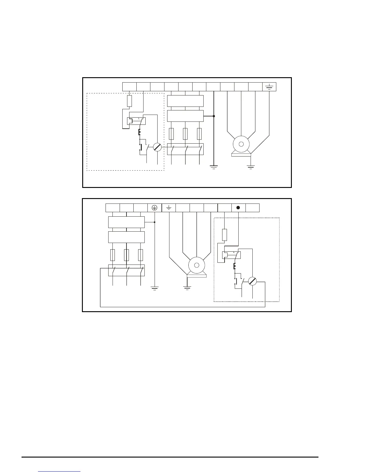
Figure 5-1 Commander SE size 2 to 4 power terminal connections
Figure 5-2 Commander SE size 5 power terminal connections
L1 L2
L2
L1
+
-
L3 PEDBR U V W
Optional RFI
filter
Optional
line reactor
Fuses
L3
Supply
Ground
Mains
Suppl
y
Motor
Motor
Ground
Start/
Reset
Stop
Optional
Thermal
protection
device
Braking
Resistor
Optional
Motor
Ground
L1 L2
L2
L1
+
_
L3 U V W
Optional RFI
filter
Optional
line reactor
Fuses
L3
Mains
Supply
Motor
Motor
Ground
Start/
Reset
Stop
Thermal
protection
device
Braking
Resistor
Supply
Ground
Optional
Optional
Motor
Ground

Table of Contents

Other manuals for Control Techniques COMMANDER SE

Questions and Answers:

Question and Answer IconNeed help?

Do you have a question about the Control Techniques COMMANDER SE and is the answer not in the manual?

Control Techniques COMMANDER SE Specifications

General IconGeneral
BrandControl Techniques
ModelCOMMANDER SE
CategoryController
LanguageEnglish

Related product manuals