186 Commander SE Advanced User Guide
Issue Number: 4
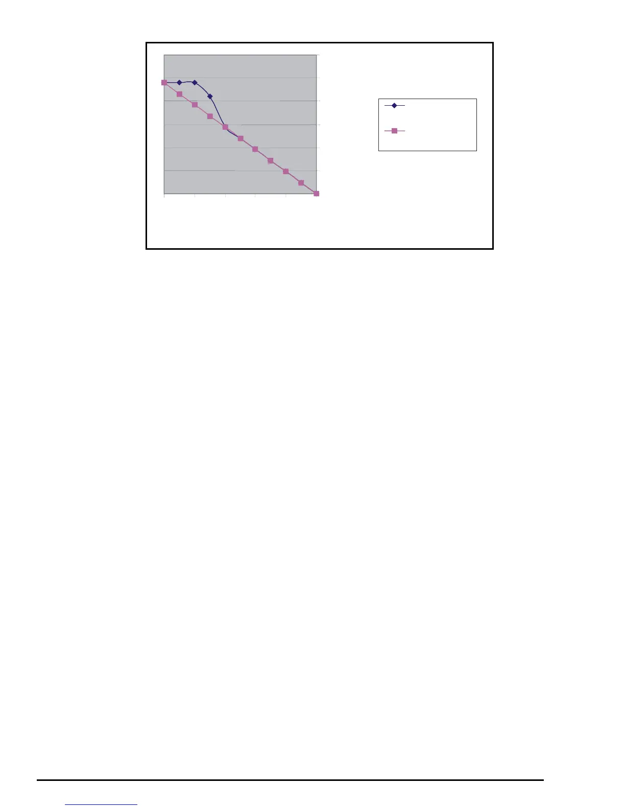
V/f curve during deceleration
12.24 Variable Trim
In some applications, it may be necessary to achieve the same % trim across a wide range of set point frequencies. The
following set-up allows approximately 10% trim regardless of the set-point frequency.
Parameter set-up
1.21 = 500 Preset speed 1 to 500
7.10 = 0 Analog input 1 destination set to 0
7.14 = 0 Analog input 2 destination set to 0
12.08 = 1.03 Variable selector source 1 to Pre-ramp reference
12.11 = 14.13 Variable selector output to PID high limit
14.02 = 7.01 PID main reference source to analog input 1 monitor
14.03 = 7.02 PID reference source to analog input 2 monitor
14.04 = 1.21 PID feedback source to preset speed 1
14.11 = 0 PID integral gain to 0
14.14 = 0 PID low limit to 0
14.15 = 0.18 PID scaling set to 0.18
14.16 = 1.36 PID output to analog reference 1
14.18 = 1 PID symmetrical limit selector set
14.08 = 1 PID enabled
Perform a Save routine: xx.00 = 1000 and press red Stop / Reset button on the drive
Parameter 14.15 can be increased or decreased slightly to give greater or less than 10 % trim.
The above set-up will give a approximately 10% trim on 50 or 60Hz set-ups. If the maximum speed is set greater than this,
the value of parameter 14.15 should be reduce accordingly to give the required % trim.
Operation
The set speed of the drive is controlled by a potentiometer on terminal 2, analog input 1.
The trim is controlled by a current signal on terminal 5, analog input 2. When this signal gives a value of 50.0% in parameter
7.02, analog input 2 monitor, no trim is provided. When this value is 0.0, the maximum value of trim is subtracted from the
output frequency. When this value is 100.0, the maximum value of trim is added from the output frequency.
The PID loop is used to either add or subtract this trim value to or from the main reference provided by analog input 1.
To keep the same % trim regardless of the speed of the motor, the drive uses the pre-ramp reference to write to the PID high
and low limits. This value along with the PID scaling allows the % of trim to remain the same as the main speed reference is
changed.
Example
If the main speed reference is 10Hz, the trim will be 10Hz +/-10%. Therefore the trim will be from 9Hz to 11Hz.
If the main speed reference is 40Hz, the trim will be 40Hz +/-10%. Therefore the trim will be from 36Hz to 44Hz.
0
50
100
150
200
250
300
01020304050
Output Frequency
Motor Volts - Flux
Braking
Motor Volts -
Standard Set-Up
Motor volts