66 Commander SE Advanced User Guide
Issue Number: 4
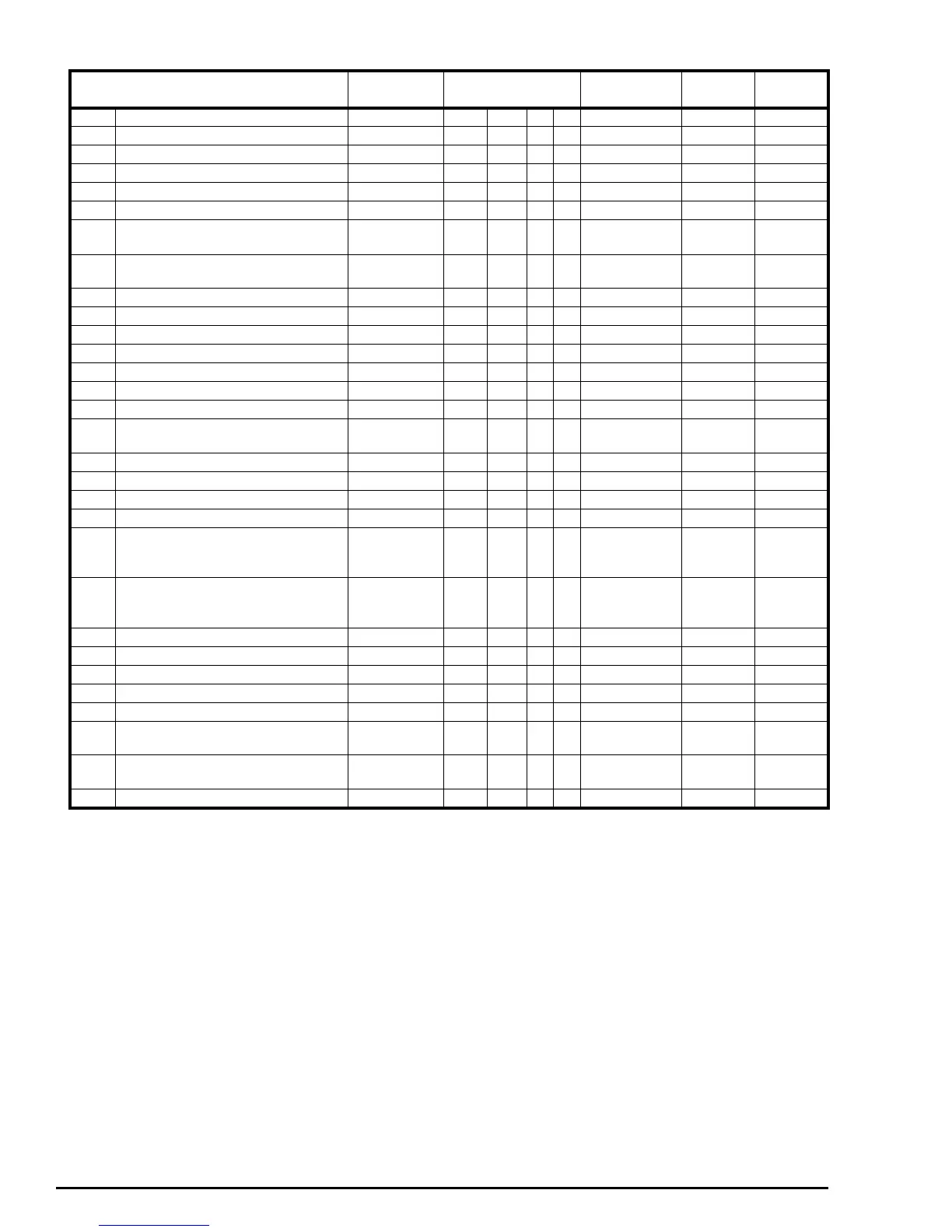
3.8 Menu 8: Digital inputs and outputs
Parameter Range Type Default Setting
Update
Rate
8.01 Digital input / output 1 (Terminal 8) 0 or 1 RO Bit P L1
8.02 Digital input 2 (Terminal 9) 0 or 1 RO Bit P L1
8.03 Digital input 3 (Terminal 10) 0 or 1 RO Bit P L1
8.04 Digital input 4 (Terminal 11) 0 or 1 RO Bit P L1
8.05 Digital input 5 (Terminal 12) 0 or 1 RO Bit P L1
8.06 Digital input 6 (Terminal 13) 0 or 1 RO Bit P L1
8.07
Relay output indicator (Terminals 15 &
16)
0 or 1 RO Bit P L1
8.08~
8.10
Not used
8.11 Digital input / output 1 invert 0 or 1 RW Bit 0 L1
8.12 Digital input 2 invert 0 or 1 RW Bit 0 L1
8.13 Digital input 3 invert 0 or 1 RW Bit 0 L1
8.14 Digital input 4 invert 0 or 1 RW Bit 0 L1
8.15 Digital input 5 invert 0 or 1 RW Bit 0 L1
8.16 Digital input 6 invert 0 or 1 RW Bit 0 L1
8.17 Relay state invert 0 or 1 RW Bit 0 L1
8.18~
8.20
Not used
8.21 Digital input 1 destination / output source 0.00 ~ 21.51 RW Uni R P P10.03 I
8.22 Digital input 2 destination 0.00 ~ 21.51 RW Uni R P P06.29 I
8.23 Digital input 3 destination 0.00 ~ 21.51 RW Uni R P P06.30 I
8.24 Digital input 4 destination 0.00 ~ 21.51 RW Uni R P P06.32 I
8.25 Digital input 5 destination 0.00 ~ 21.51 RW Uni R P
Reference
select
dependant
I
8.26 Digital input 6 destination 0.00 ~ 21.51 RW Uni R P
Reference
select
dependant
I
8.27 Relay source 0.00 ~ 21.51 RW Uni R P P10.01 I
8.28 Not used
8.29 Logic input polarity 0 ~ 1 RW Bit R P 1 I
8.30 Not used
8.31 Activate digital output 1 0 ~ 1 RW Bit R 1 L1
8.32~
8.38
Not used
8.39
Disable digital inputs 5 and 6 auto
selection
0 ~ 1 RW Bit 0 B
8.40 Digital input 6 as thermistor input 0 ~ 1 RW Bit R 0 L1