172 Commander SE Advanced User Guide
Issue Number: 4
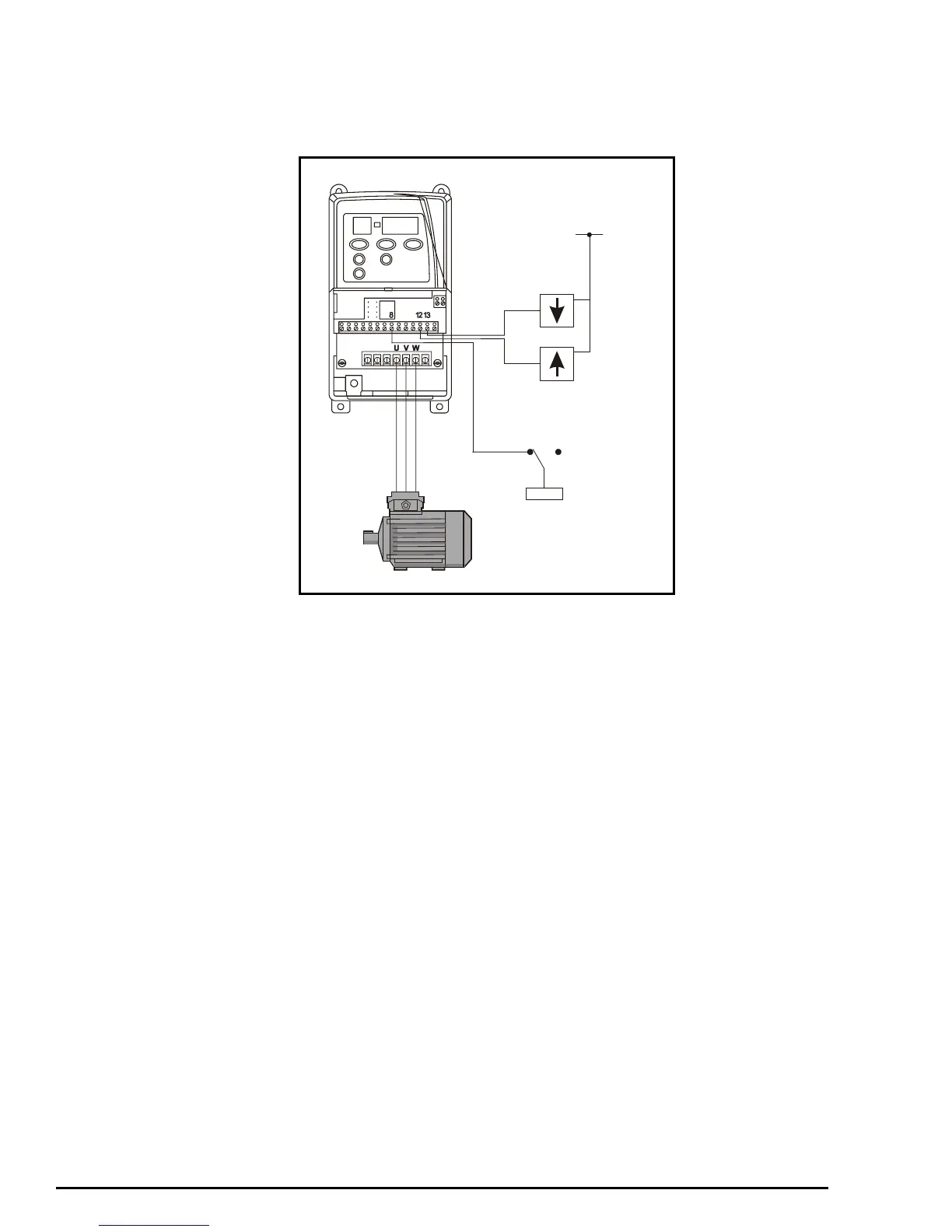
12.11 Motorised potentiometer set-up
The Commander SE has the possibility to emulate a motorised potentiometer by simply supplying two logic input signals to
increase or decrease the potentiometer. The output of the potentiometer may be routed to control any of the drives non-bit
parameters such as speed, torque or current limit. Additionally the function may be configured to reset upon power cycling, or
to memorise its value.
Parameter set-up
8.39 = 1 Disable auto set-up of terminals 12 and 13.
8.31 = 0 Digital input 1 (terminal 8) set as an input.
8.21 = 9.28 Digital input 1 (terminal 8) assigned as RESET for motorised potentiometer.
8.25 = 9.26 Digital input 5 (terminal 12) assigned as motorised potentiometer increase.
8.26 = 9.27 Digital input 6 (terminal 13) assigned as motorised potentiometer decrease.
9.23 = ? This adjusts the rate of increase / decrease.
7.10 = 0 Analog input 1 not used.
9.25 = 1.36 Motorised potentiometer destination assigned to analog reference 1.
Perform a Save routine: xx.00 = 1000 and press red Stop / Reset button on the drive.
RESET
1
0
DECREASE
INCREASE
+24V