Commander SE Advanced User Guide 109
Issue Number: 4
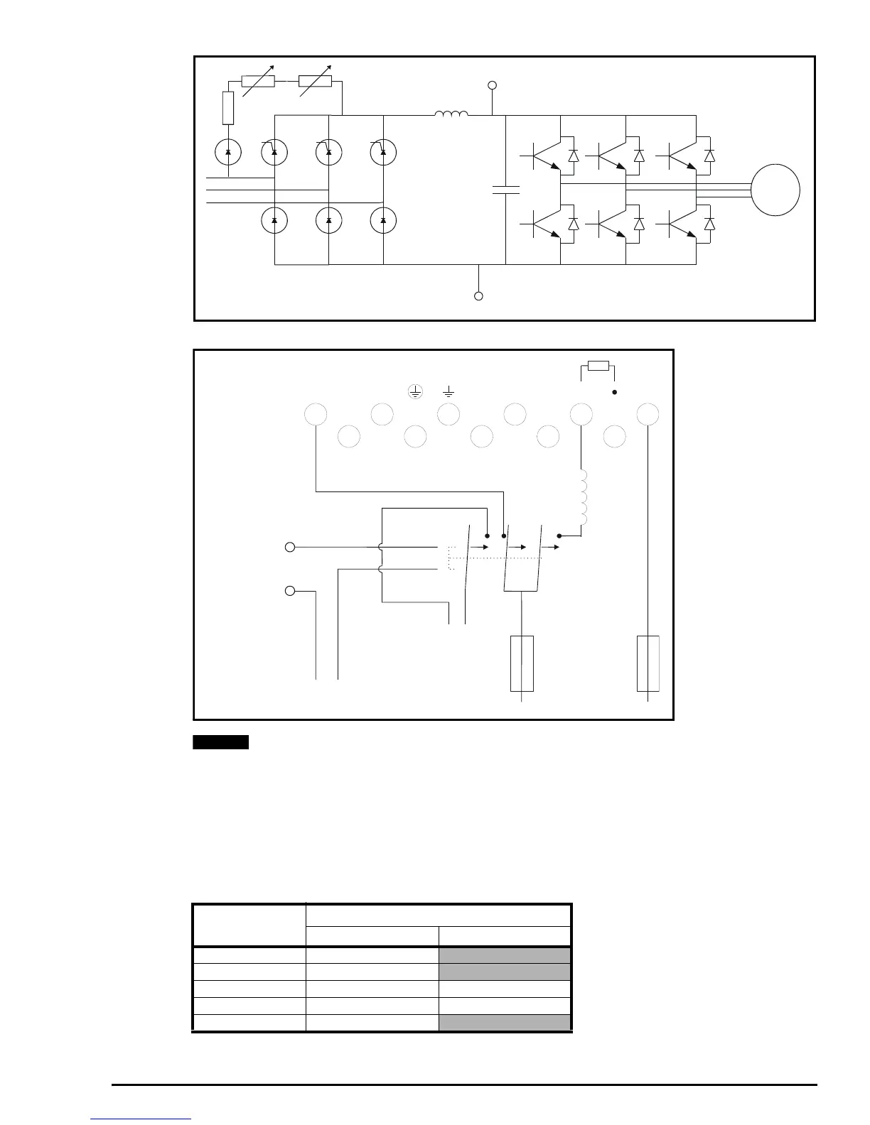
Figure 4-6 Commander SE size 5 power circuit layout
Figure 4-7 Method of powering up the Commander SE size 5 by the DC bus using the drives internal inrush resistor
The source of the relay must NOT be changed from Drive Healthy. For relay ratings refer to the Commander SE User
Guide.
4.3 Gland plate holes
A slot has been provided in the gland plate of sizes 1 to 4 for control cables. One of the gland plate holes can be used for
control cables but this should be separate from any power cables.
Size 5 has a separate gland plate with two 22mm holes for the control cables.
Table 4-1 Gland plate hole dimensions
Motor
+DC bus
-DC bus
L1 L2 L3 U V W + -
DC Supply with each
drive individually fused
NC NO
Soft start
contactor
110V ac supply for soft
start contactor coil
Contactor coil supply
must be wired through
the drive healthy relay
Terminal 15
Terminal 16
Contactor
coil
DC Choke
NO
Normally Open Auxiliary
contact must be hard
wired with the drive
enable on terminal 9
NOTE
Drive size
Number of holes in power terminal gland plate
22mm 27mm
13
23
31 2
42 2
511