114 Commander SE Advanced User Guide
Issue Number: 4
4.7 Calculating the enclosure size
1. Add the dissipation figures from section section 4.8 Commander SE losses on page 116 for each drive that is to be
installed in the enclosure.
2. If an RFI filter is to be used with each drive, add the dissipation figures from section 4.8 Commander SE losses on
page 116 for each RFI filter that is to be installed in the enclosure.
3. If the braking resistor is to be mounted inside the enclosure, add the average power figures for each braking resistor that
is to be installed in the enclosure.
4. Note the total heat dissipation (in Watts) of any other equipment to be installed in the enclosure.
5. Add the heat dissipation figures obtained (as appropriate) from points 1, 2, 3 and 4 above. This gives a figure in Watts for
the total heat that will be dissipated inside the enclosure.
Calculating the size of a sealed enclosure
The enclosure transfers internally generated heat into the surrounding air by natural convection (or external forced air flow);
the greater the surface area of the enclosure walls, the better is the dissipation capability. Only the surfaces of the enclosure
that are unobstructed (not in contact with a wall or floor) can dissipate heat.
Calculate the minimum required unobstructed surface area A
e
for the enclosure from:
Where:
A
e
Unobstructed surface area in m
2
(1m
2
= 10.8 ft
2
)
T
amb
Maximum expected ambient temperature in °C outside the enclosure
T
i
Maximum permissible ambient temperature in °C inside the enclosure
P Power in Watts dissipated by all heat sources in the enclosure
k Heat transmission coefficient of the enclosure material in W/m
2
/°C
Example
To calculate the size of an enclosure for the following:
• Two SE23400400 models
• Each drive to operate at 6kHz
PWM switching frequency
• RFI filter for each drive
• Braking resistors are to be mounted outside the enclosure
• Maximum ambient temperature inside the enclosure: 40°C
• Maximum ambient temperature outside the enclosure: 30°C
Dissipation of each drive: 158W
Dissipation of each RFI filter: 10.1W (max)
Total dissipation: 2 x (158 + 10.1) = 336.2W
The enclosure is to be made from painted 2mm (
3
/
32
in) sheet steel having a heat transmission coefficient of 5.5W/m
2
/°C.
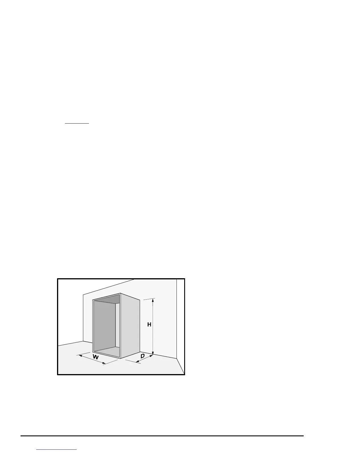
Only the top, front, and two sides of the enclosure are to be free to dissipate heat.
Figure 4-9 Enclosure having front, sides and top panels free to dissipate heat
Insert the following values:
T
i
40°C
T
amb
30°C
k 5.5
P 336.2W
A=
P
k(T - T )
e
iamb