Commander SE Advanced User Guide 9
Issue Number: 4
Table 1-1 RS Components Part Numbers
The instructions provided are only applicable for Stewart manufactured RJ45 connectors.
1.2 Serial communications connections
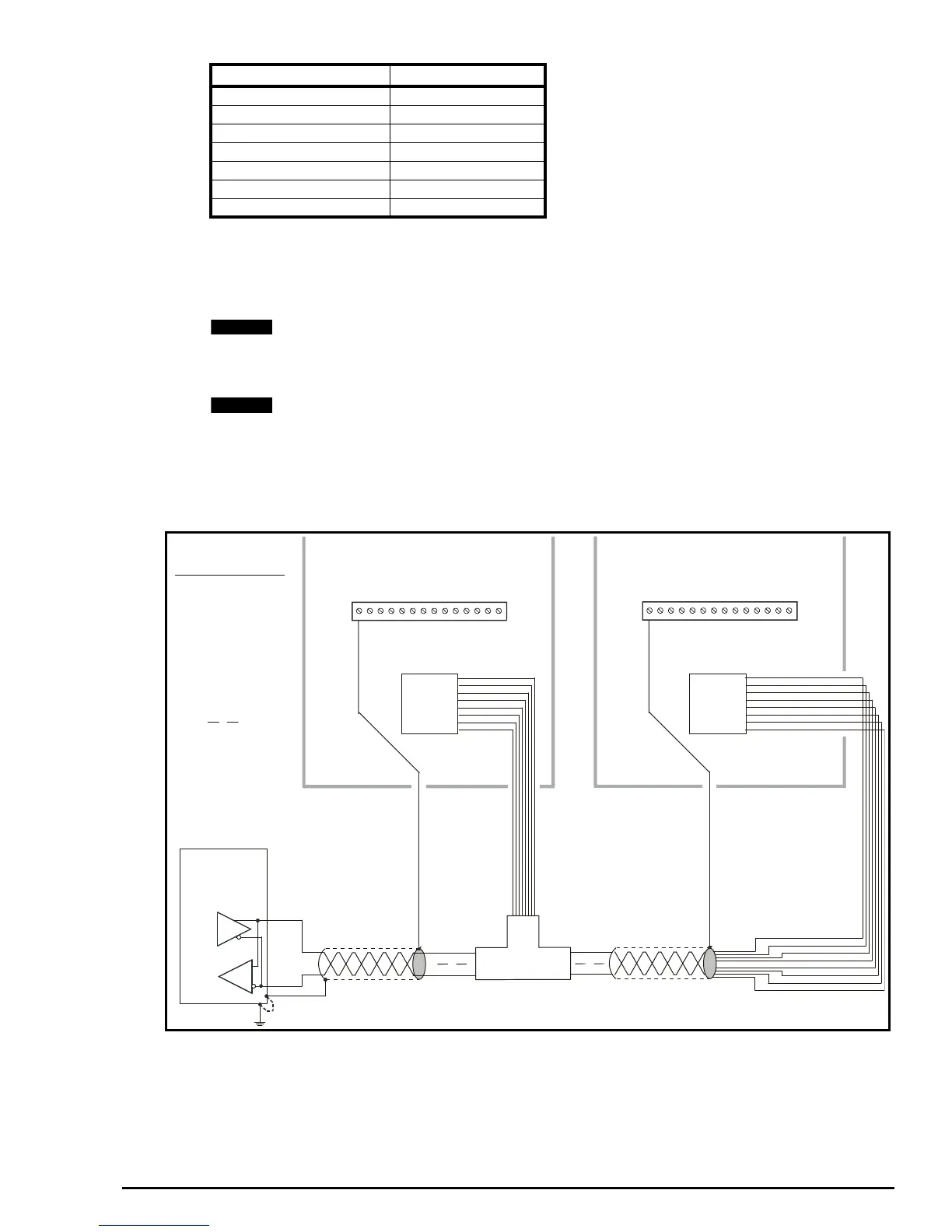
If more than one drive is to be connected to a serial link, make connections as shown in the diagram below.
• The serial communications cable must be shielded. The shield(s) must be connected as shown in the diagram below:
A data communications cable should not run parallel to any power cables, especially ones that connect drives to
motors. If parallel runs are unavoidable, ensure a minimum spacing of 300mm (12 in.) between the communications
cable and the power cable.
Cables crossing one another at right-angles are unlikely to give trouble. The maximum cable run length for a EIA485
link is 1,200 metres (4,000 feet).
If more than one drive is connected to the host computer, please adjust the serial address of each drive to ensure that each
drive has a unique address.
Therefore with the drive in the above condition, all commissioning and operation can be done using the EIA485
communication link.
T-Bar connector / splitter from Insight.
Part No: CNX3A02KNW
www.insight.com
Pin 6 TX Enable
The TX Enable pin is a 0 to 5V output from the Drive that can be used to externally control and switch the buffers on a serial
communications converter from transmit to receive and vice-versa. An example of a converter that can be used with this
signal is the Amplicon 485Fi.
Description Part Number
Stewart RJ45 Connectors 290-4780
Ferrule Crimp Hand tool 290-4853
5.2mm Cable Crimp 290-4875
4.5mm Cable Crimp 290-4869
RJ45 Hand tool 290-4796
Shielded Die 290-4847
Unshielded Die 290-4825
NOTE
NOTE
1
2
3
4
5
6
7
8
RJ45
RJ45 T-BAR
CONNECTOR
SYSTEM
CONTROLLER
(RS485)
TRANSCEIVER
Tx / Rx
Tx / Rx
Drive 1 Drive 2
RJ45 CONNECTOR
PIN 1 TERMINATION
RESISTOR
PIN 2 Rx Tx
PIN 3 0V
PIN 4 +26V
PIN 5 NOT USED
PIN 6 TX ENABLE
PIN 7 Rx Tx
PIN 8 LINKED TO PIN 7
1
2
3
4
5
6
7
8
RJ45
1
14
1
14
0V
Tx / Rx
Tx / Rx