108 Commander SE Advanced User Guide
Issue Number: 4
4.1.1 Power terminal torques
4.1.2 Thermal protection for an optional braking resistor
Figure 4-2 and Figure 4-3 show a typical circuit arrangement for braking resistor protection. This thermal
protection must disconnect the AC supply from the drive if the resistor becomes overloaded. (Do not use
overload opening contact in line with braking resistor).
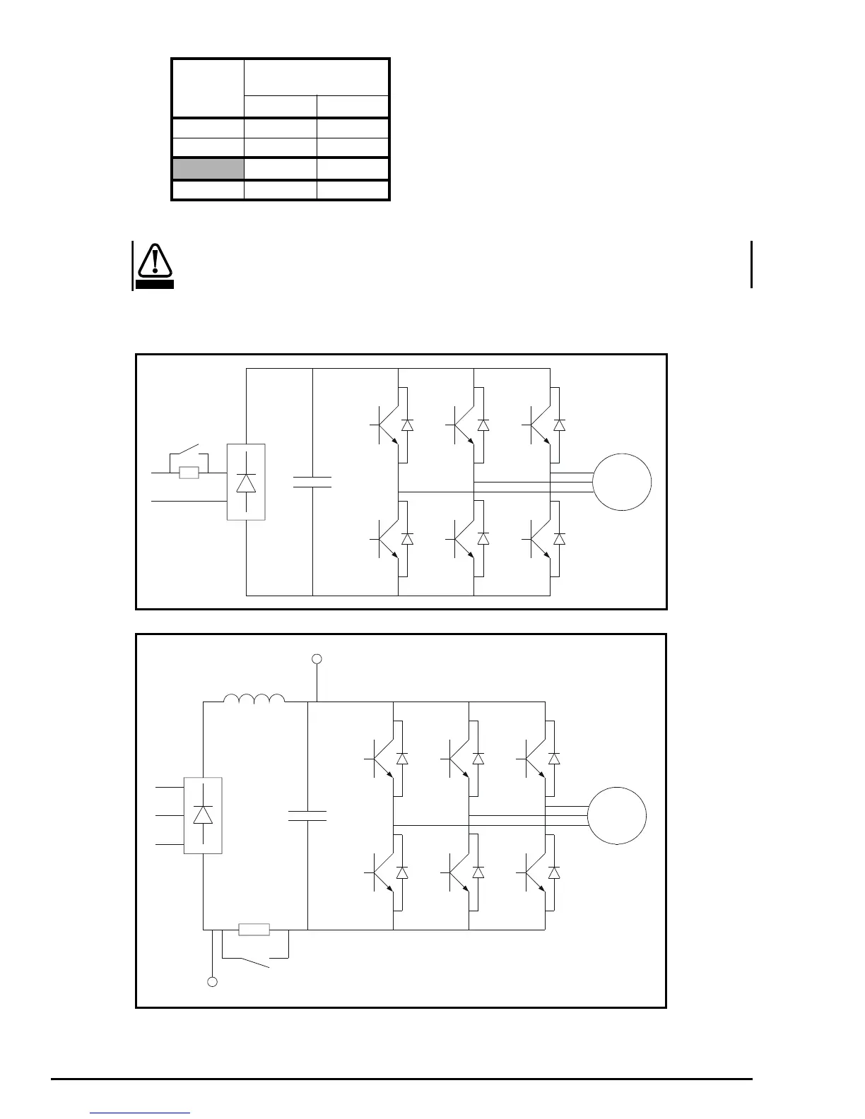
4.2 Commander SE power circuit layouts
Figure 4-4 Commander SE size 1 power circuit layout
Figure 4-5 Commander SE size 2, 3 and 4 power circuit layout
Commander SE sizes 2, 3 and 4 can be powered directly on to its + and - DC terminals from a DC power supply without any
external softstart circuitry.
Commander SE size 5 requires an external softstart circuit, see Figure 4-7.
Drive size
Maximum power terminal
screw/stud torque
Nm lb in
1 & 2 1 9
3 & 4 2 18
Nm lb ft
51511
WARNING
Motor
Motor
+DC bus
-DC bus
* Not on Commander
SE size 2
*