Commander SE Advanced User Guide 113
Issue Number: 4
Provide fuse or other over-current protection in status relay circuit.
4.6.2 Digital inputs sample times
The digital I/O sample times for the control terminals are shown in Default configuration on page 111. These times are correct
but are the times for the control microprocessor to sample the digital inputs. The actual time for the drive to act upon these
signals will be slightly longer.
The digital input will be sampled within 1.5ms, then it takes between 4.5 to 6ms for this information to be passed across the
serial communications link between the control microprocessor and the machine control DSP (Digital Signal Processor). The
DSP runs on a 6kHz cycle and the information is processed as soon as it receives the information from the serial comms link.
Example:
The maximum time taken to disable the drive:
Control microprocessor update rate: 1.5ms maximum
Time across serial comms link and DSP to process information: 6.0ms maximum
Therefore it will take a maximum of 7.5ms for the drive to disable from receiving the disable signal.
4.6.3 Digital output update rate
The time taken for the digital output to be updated will depend upon the parameter programmed to the digital output source
(parameter 8.21). The DSP is run on a 6kHz cycle and the information is passed across the serial comms link on this cycle
time.
Example:
The maximum update time for the drive healthy relay to be set:
DSP to process information and time across the serial comms link: 6.0ms maximum
Control microprocessor update rate: 1.5ms maximum
Therefore it will take a maximum of 7.5ms for the drive healthy relay to be set to indicate a fault.
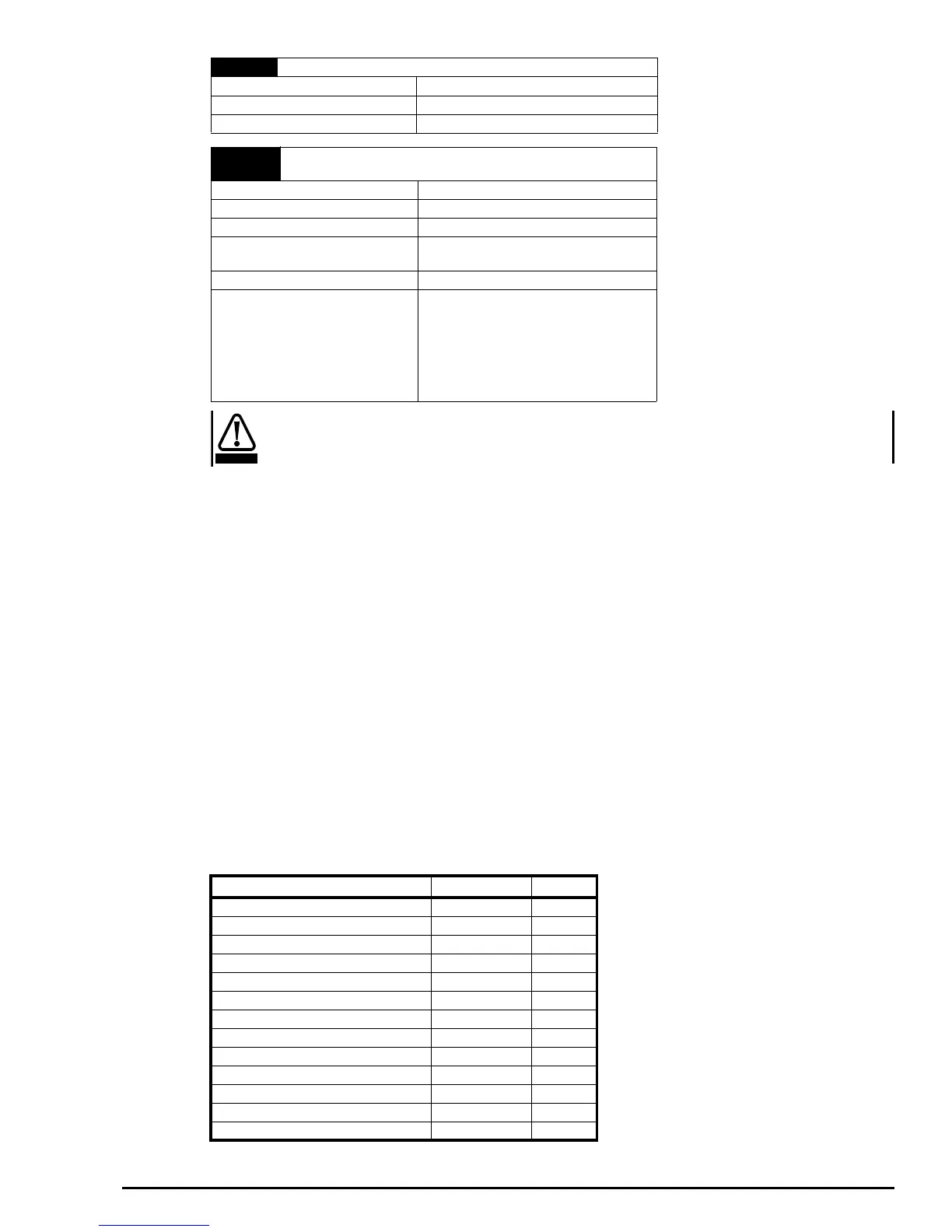
Task Routine Levels:
The timing of each parameter can be seen in the single line parameter description at the beginning of each menu.
14 +24V output
Voltage accuracy ± 10%
Maximum output current 100mA
Protection tolerates continuous short circuit to 0V
15
16
Status relay (Normally open)
Function Drive Healthy
Voltage rating 240VAC /30VDC
Current rating 2A/6A (resistive)
Contact isolation
2.5kVAC (meets IEC664-1 with over
voltage category II)
Update time 6ms
Operation of contact
OPEN - AC supply removed from drive
- AC supply applied to drive with the drive
in a tripped condition
CLOSED
- AC supply applied to drive with the drive
in a ‘ready to run’ or ‘running’ condition
(not tripped)
WARNING
Level Abbreviation Time
Level 1 L1 1.5ms
Level 2 L2 6.0ms
Level 3 L3 22ms
Background B
Background slow and motor changed BS, MC
Background fast and motor changed BF, MC
Background fast BF
Background fast and L1 BF, L1
Background and Reset BF, I
Reset I
Motor changed MC
Reset and Level 1 I, L1
Autotune A