38 Commander SE Advanced User Guide
Issue Number: 4
*Units: % of rated active current
Main torque reference parameter. A positive value is required for torque to be applied in the forward direction, and a negative
value is required for torque to be applied in the reverse direction.
For a negative value, program a digital input to the analog input invert bit. This will give a negative value on the analog input
destination parameter.
If operating in torque control (4.08 = 1), due to small errors in current measurement at low frequencies, with zero torque
reference and light load, the drive may allow the motor to turn. The direction of rotation, while in torque control, is determined
by the polarity of the torque reference. Therefore at power up with zero torque reference and with the drive enabled the motor
may turn in either direction. The reason for this is because any error in the current feedback may be a positive or negative
value. If the error is negative the motor can turn in the reverse direction and if the error is positive the motor can turn in the
forward direction.
If it is necessary to guarantee the direction of rotation at power up, while in torque control, then a small positive or negative
value must be present in 4.08.
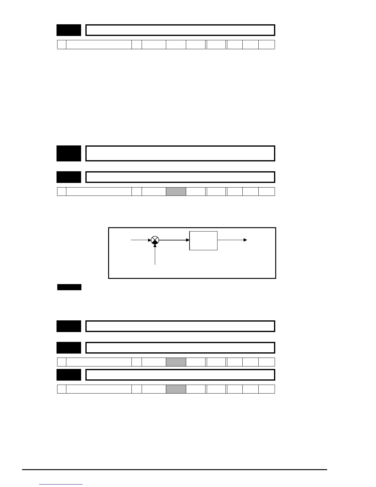
If this parameter is 0 normal frequency control is used. If this parameter is set to 1 the current demand is connected to the
current PI controller giving closed loop torque/current control as shown below. The current error is passed through
proportional and integral terms to give a frequency reference. The frequency reference is limited to the range -maximum
frequency to + maximum frequency as defined by 1.06 ±20%.
To change from speed control to torque control or vice versa, the drive must be either disabled, tripped or in stand-
by mode.
When this parameter is set to 1, slip compensation is automatically disabled to prevent overspeed trips (O.SP).
These parameters control the proportional and integral gains of the current controller. As already mentioned the current
controller either provides current limits or closed loop torque control by modifying the drive output frequency. Although the
default settings have been chosen to give suitable gains for less demanding applications it may be necessary for the user to
adjust the performance of the controller. The following is a guide to setting the gains for different applications.
4.08 Torque reference
Ú
Maximum current limit
Ö
0
*
RW Bi
4.09 ~
4.10
Unused parameters
4.11 Torque mode selector
Ú
0 or 1
Ö
0 RW Bit
4.12 Unused parameter
4.13 Current loop proportional gain
Ú
0 ~ 250
Ö
20 RW Uni
4.14 Current loop integral gain
Ú
0 ~ 250
Ö
40 RW Uni
P 04.13
I 04.14
Active
current
Current
demand
Frequency
reference
+
-
Active
NOTE