Curtis 1232E/34E/36E/38E & 1232SE/34SE/36SE Manual, os 30
15
24 NOVEMBER 2015
2 — INSTALLATION & WIRING: Throttle Wiring
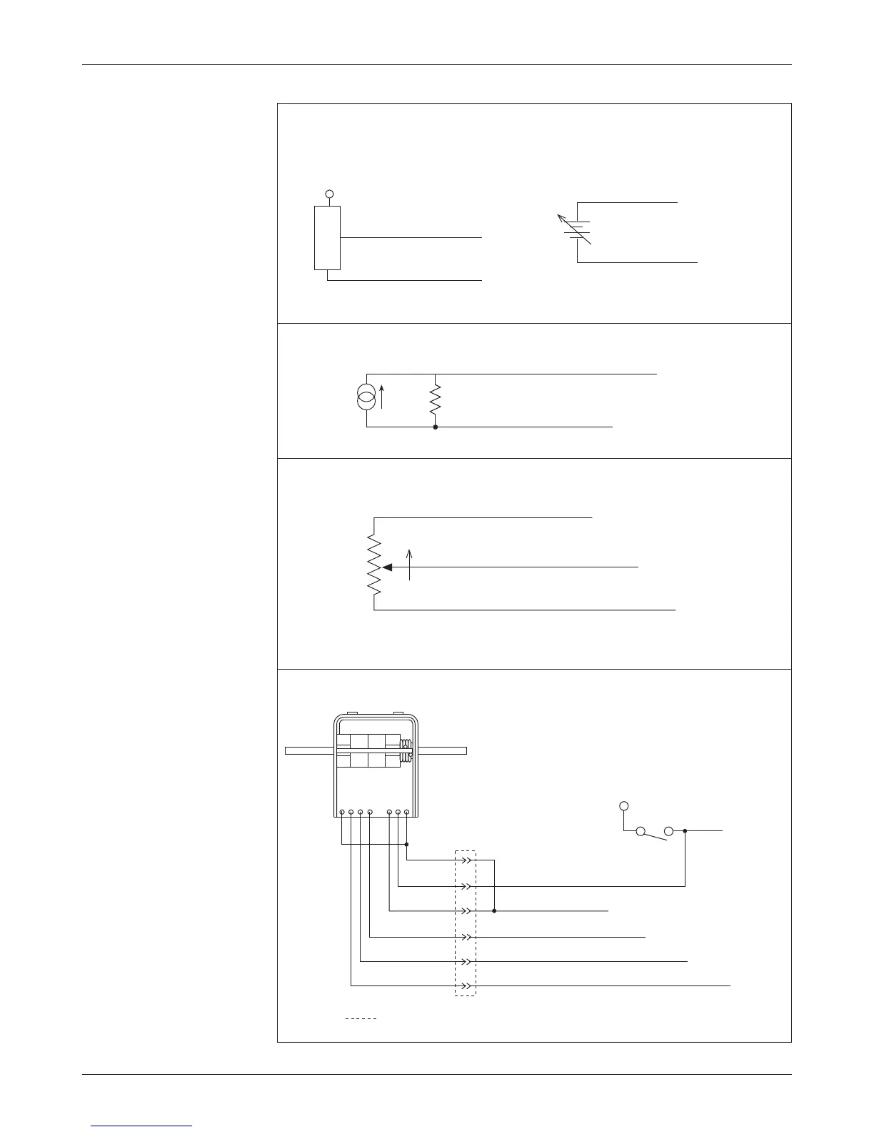
Fig. 5 Wiring for Type 2
throttles.
Curtis ET-XXX Electronic Throttle
GREEN
ORANGE
BLACK
BLACK/WHITE
WHITE
WHT/BRN
B+
KEYSWITCH
connector
WHT/GRN
Reverse input (Pin 33)
KSI (Pin 1)
Throttle Pot Wiper input (Pin 16)
Forward input (Pin 22)
I/O Ground Return (Pin 7)
Voltage Source
Current Source
3-wire Potentiometer
+
+
-
SENSOR OUTPUT (0–5V)
SENSOR
SENSOR GROUND
I/O Ground Return (Pin 7)
Pot Wiper input (Pin 16 or 17)
Sensor-referenced 0–5V source Ground-referenced 0–5V source
Pot Wiper input (Pin 16 or 17)
I/O Ground Return (Pin 7)
Pot Wiper input (Pin 16 or 17)
I/O Ground Return (Pin 7)
R
throttle
I
source
1kΩ–10kΩ
FASTER
NOTE: Pins 15 and 16 are used together in the throttle pot; Pins 27 and 17 in the brake pot.
Pot Low input (Pin 18)
Pot High output (Pin 15 or 27)
Pot Wiper input (Pin 16 or 17)