24
Curtis 1232E/34E/36E/38E & 1232SE/34SE/36SE Manual, os 30
24 NOVEMBER 2015
2 — INSTALLATION & WIRING: I/O Signal Specifications
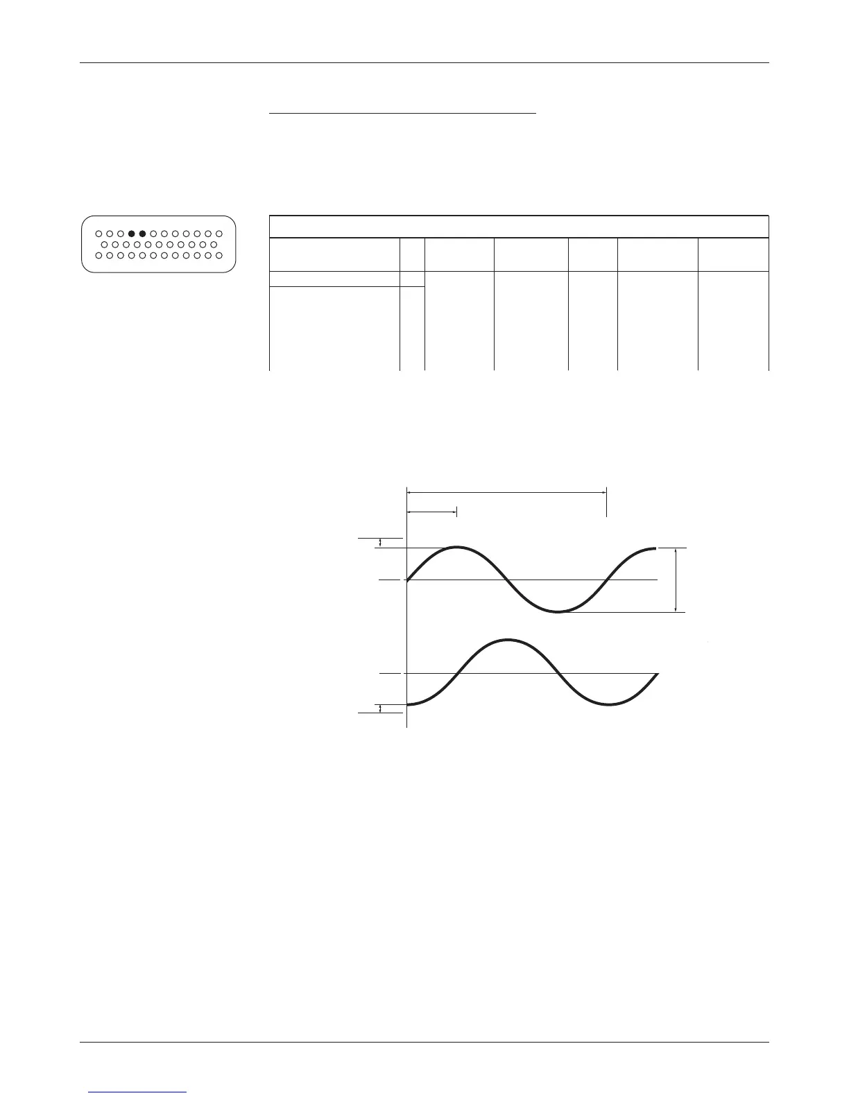
Position feedback input: sin/cos sensor
Two control lines are internally configured to read a sin/cos sensor. Position
Feedback A (pin 31) provides the sine signal, and Feedback Position B (pin 32)
provides the cosine signal. e device must be set up with one sensor revolution
per mechanical revolution.
SIN/COS SENSOR INPUT SPECIFICATIONS
operating
input max protected esd
signal name pin voltage
impedance freq. voltage tolerance
Position Feedback A 31 0 to 5 V 150 kΩ 500Hz - 5Vto ± 8kV
Position Feedback B 32 for voltages (MaxV + 10 V) (direct strike)
≤5V;
75 kΩ
for voltages
> 5 V
ese signal tolerances must be maintained over the controller’s voltage and
temperature ranges and the vehicle’s speed range. e sin/cos waveform peaks
must be away from V
dd
and ground by at least 0.5 V. In the example shown in
the timing diagram below, V
dd
= 5 V.
360° mechanical (1 cycle)
V
pp
V
A
V
B
0.5 V
V
dd
Gnd
V
dd
2
V
dd
2
90°
0.5 V