Curtis 1232E/34E/36E/38E & 1232SE/34SE/36SE Manual, os 30
21
24 NOVEMBER 2015
2 — INSTALLATION & WIRING: I/O Signal Specifications
Analog output
A single line is available as a low power analog output and is intended to drive
instrumentation such as a battery discharge indicator. is output is generated
from a filtered PWM signal and has about 1% ripple. e 2% settling time is
<25ms for a 0–5V step and <30 ms for a 0–10V step. is output line is pro-
tected against shorts to B+ or B-. Note: e 1232E/SE has no analog output.
POWER SUPPLY OUTPUT SPECIFICATIONS
output
output protected esd
signal name pin voltage
current voltage tolerance
+12VOut 25 11.5to14.5V 200mAmax - 1Vto ± 8kV
+5V Out 26 5 V ±5% (combined total) (MaxV + 10 V) (direct strike)
I/O Ground 7 n/a 500 mA max not protected
13
24
1
23
35
12
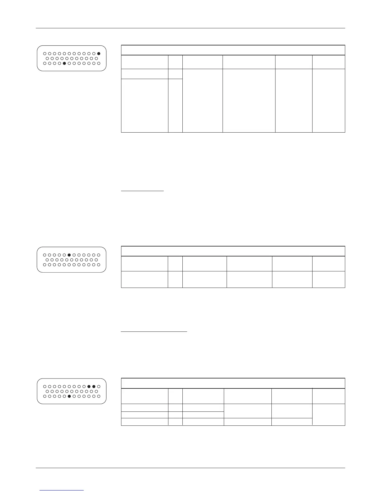
ANALOG OUTPUT SPECIFICATIONS
output
output protected esd
signal name pin voltage
current voltage tolerance
AnalogOut 30 0to10V 10mA - 1Vto ± 8kV
(MaxV + 10 V) (direct strike)
13
24
1
23
35
12
Power supply outputs
Two lines provide auxiliary output power for low power circuits such as elec-
tronic throttles, LED indicators, displays, position encoder, and remote I/O
boards. I/O Ground (at pin 7) is the return line for these low power devices.
Both power supply outputs are protected against shorts to B+ or B-.
13
24
1
23
35
12
ANALOG INPUT SPECIFICATIONS
operating
input protected esd
signal name pin voltage
impedance
*
voltage tolerance
Analog 1 24 0 to 10 V in 24-36V models: - 10Vto ± 8kV
Analog 2 8 1024 steps 6.9 kΩ, 7.1 kΩ (MaxV + 10 V) (direct strike)
36-48V models:
10.5 kΩ, 11.0 kΩ
48-80V models:
23.8 kΩ, 28.1 kΩ
72-96V models:
n/a, 28.1 kΩ
*
The rst value is for 1232E/SE and 1234E/SE controllers,
and the second value is for 1236E/SE and 1238E controllers.