14
Curtis 1232E/34E/36E/38E & 1232SE/34SE/36SE Manual, os 30
24 NOVEMBER 2015
For potentiometers, the controller provides complete throttle fault
protection that meets all applicable EEC regulations. For voltage throttles, the
controller protects against out-of-range wiper values, but does not detect wiring
faults; it is therefore the responsibility of the OEM to provide full throttle fault
protection in vehicles using voltage throttles.
rottle types 1–3 use the forward and reverse inputs (switches 7 and 8) in
addition to the throttle pot input to define the throttle command (see Figure 15,
page 114). rottle types 4 and 5 do not use the forward and reverse inputs.
Wiring for the most common throttles is described in the following text
and shown in the accompanying illustrations. If a throttle you are planning to
use is not covered, contact your Curtis distributor or support engineer.
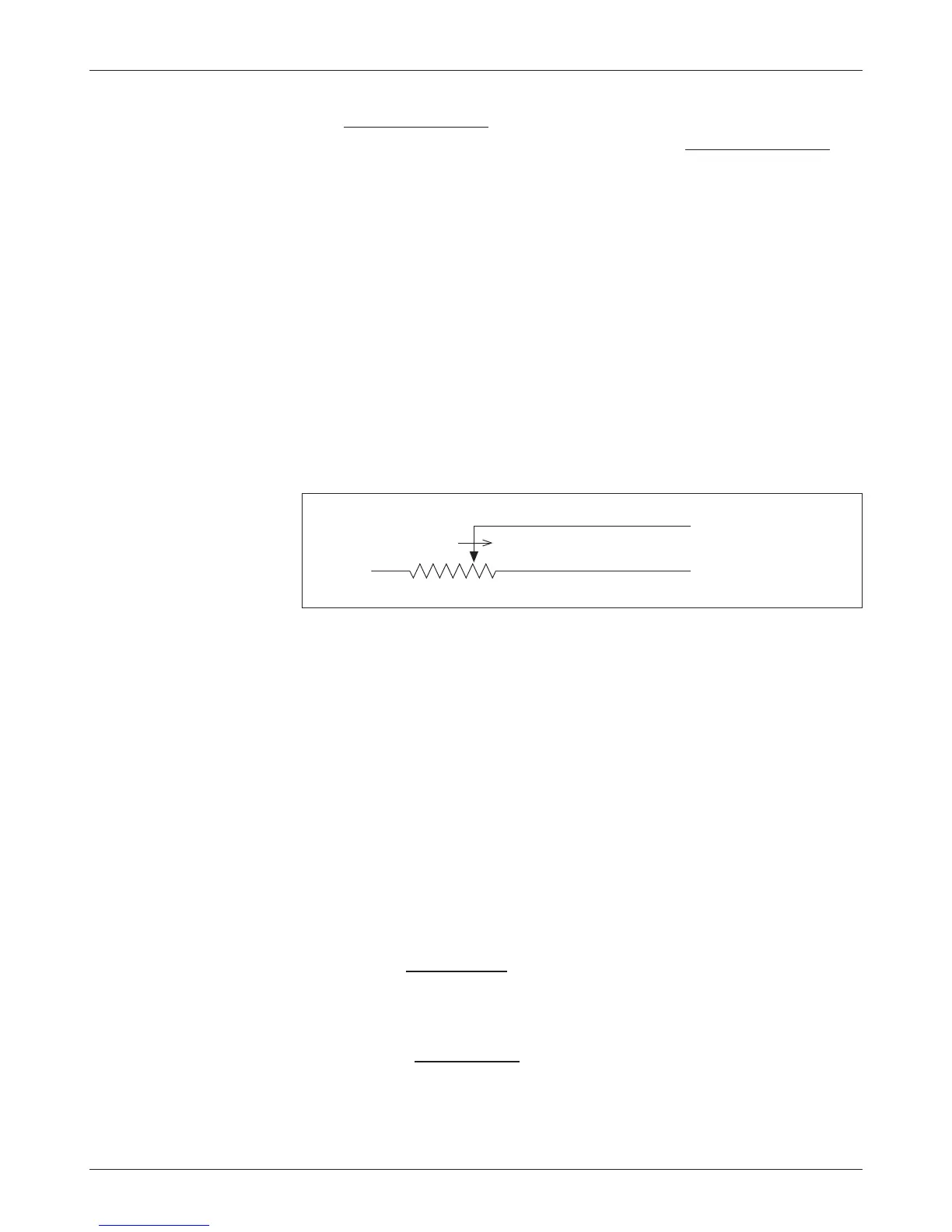
Throttle Type 1
For these 2-wire resistive potentiometers, shown in Figure 4, full throttle request
corresponds to 0 Ω measured between the pot wiper pin and the Pot Low pin.
2 — INSTALLATION & WIRING: Throttle Wiring
Fig. 4 Wiring for Type 1
throttles.
Pot Low input (Pin 18)
Pot Wiper input (Pin 16 or 17)
FASTER
Broken wire protection is provided by the controller sensing the current ow
from the pot wiper input (pin 16 or 17) through the potentiometer and into
Pot Low (pin 18). If the Pot Low input current falls below 0.65 mA, a throttle
fault is generated and the throttle request is zeroed. Note: Pot Low (pin 18)
must not be tied to ground (B-).
Throttle Type 2
With these throttles, the controller looks for a voltage signal at the wiper input.
Zero throttle request corresponds to 0 V and full throttle request to 5 V. A variety
of devices can be used with this throttle input type, including voltage sources,
current sources, 3-wire pots, and electronic throttles. e wiring for each is
slightly dierent, as shown in Figure 5, and they have varying levels of throttle
fault protection.
When a voltage source is used as a throttle, it is the responsibility of the
OEM to provide appropriate throttle fault detection. For ground-referenced
0–5V throttles, the controller will detect open breaks in the wiper input but
cannot provide full throttle fault protection.
To use a current source as a throttle, a resistor must be added to the
circuit to convert the current source value to a voltage; the resistor should be
sized to provide a 0–5V signal variation over the full current range. It is the
responsibility of the OEM to provide appropriate throttle fault detection.