Curtis 1232E/34E/36E/38E & 1232SE/34SE/36SE Manual, os 30
23
24 NOVEMBER 2015
2 — INSTALLATION & WIRING: I/O Signal Specifications
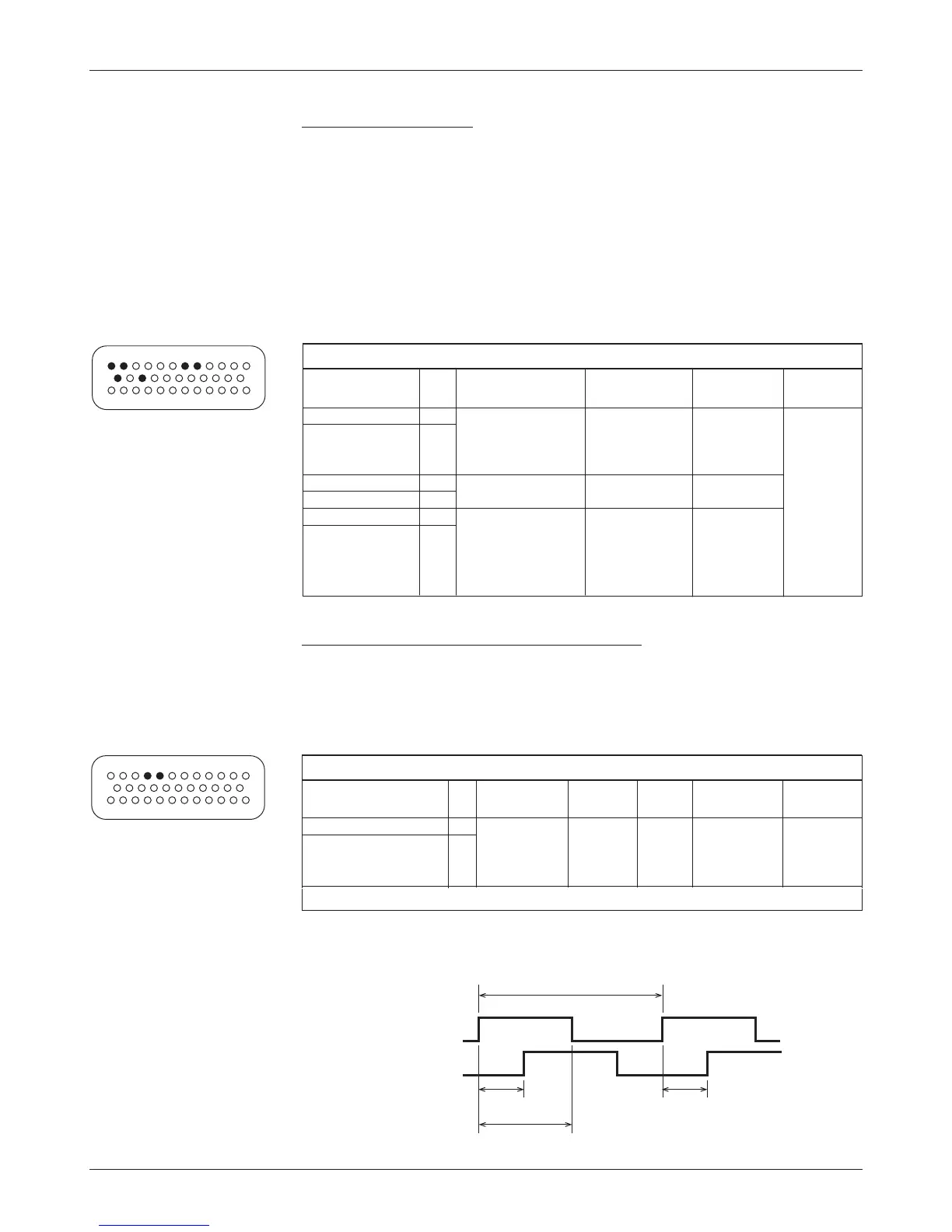
Position feedback input: quadrature encoder
Two control lines are internally configured to read a quadrature type position
encoder. e encoder is typically powered from the 5V supply (pin 26) or 12V
supply (pin 25), but can be powered from any external supply (from 5 V up to
B+) as long as the logic threshold requirements are met.
QUADRATURE ENCODER INPUT SPECIFICATIONS
logic
input max protected esd
signal name pin thresholds
impedance freq. voltage tolerance
Position Feedback A 31 Rising edge= 2 kΩ 10kHz - 5Vto ± 8kV
Position Feedback B 32 2.9 V max (internal (MaxV + 10 V) (direct strike)
Falling edge= pull-up
2.0 V min to +4.5 V)
Phase Shift 90° ±30°; Duty Cycle 50% ±10%; no signal edge can be closer than 10 µs to an adjacent edge.
ese signal tolerances must be maintained over the controller’s voltage and
temperature ranges and the vehicle’s speed range.
Channel A
Channel B
360 ° electrical (1 cycle)
>10 μs90° ±30°
180° ±18°
COMMUNICATIONS PORT SPECIFICATIONS
supported
protected esd
signal name pin protocol/devices
data rate voltage tolerance
CANH 23 CANopen, upto1Mbit/s -5Vto ± 8kV
CANL 35 other 11-bit or (MaxV + 10 V) (direct strike)
29-bitidentier
protocols
CAN Term H 21 (no connection
CAN Term L 34
to external wiring)
Serial TX 28 Curtis 840 Display, as required, -0.3 to 12 V
Serial RX 29 1313 Handheld 9.6 to 56 kbit/s
Programmer,
1314 PC Program-
ming Station
13
24
1
23
35
12
Communications ports
Separate CAN and serial ports provide complete communications and pro-
gramming capability for all user available controller information.
e Curtis 1313 handheld and 1314 PC programmers plug into a con-
nector wired to pins 28 and 29, along with ground (pin 7) and the +12V power
supply (pin 25); see wiring diagram, Figure 3. e Curtis Model 840 display
can plug into the same 4-pin connector.
Wiring the CAN Term H and CAN Term L pins together provides a local
CAN termination of 120 Ω, 0.5 W; keep the length of these wires short. CAN
Term H and CAN Term L should never be connected to any external wiring.