16
Curtis 1232E/34E/36E/38E & 1232SE/34SE/36SE Manual, os 30
24 NOVEMBER 2015
When a 3-wire potentiometer is used, the controller provides full fault
protection in accordance with EEC requirements. e pot is used in its voltage
divider mode, with the controller providing the voltage source and return. Pot
High provides a current limited 5V source to the pot, and Pot Low provides
the return path. is is the throttle shown in the basic wiring diagram (Figure 3)
for the drive throttle and for the brake throttle.
e ET-XXX electronic throttle is typically used only as a drive throttle.
e ET-XXX contains no built-in fault detection, and the controller will de-
tect only open wiper faults. It is the responsibility of the OEM to provide any
additional throttle fault detection necessary.
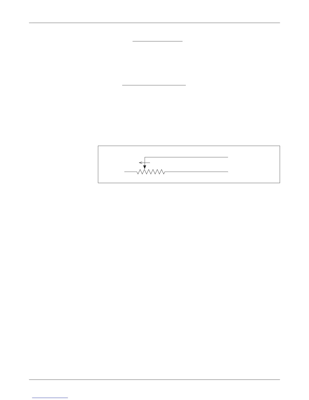
Throttle Type 3
For these 2-wire resistive potentiometers, shown in Figure 6, full throttle request
corresponds to 5 kΩ measured between the pot wiper pin and the Pot Low pin.
2 — INSTALLATION & WIRING: Throttle Wiring
Broken wire protection is provided by the controller sensing the current ow
from the wiper input (pin 16 or 17) through the potentiometer and into Pot
Low (pin 18). If the Pot Low input current falls below 0.65 mA, a throttle
fault is generated and the throttle request is zeroed. Note: Pot Low (pin 18)
must not be tied to ground (B-).
Throttle Type 4
Type 4 throttles operate in wigwag style. No signals to the controller’s forward
and reverse inputs are required; the direction is determined by the wiper input
value. Only 0–5V voltage sources and 3-wire potentiometers can be used as
Type 4 throttles. e controller interface for Type 4 throttles is the same as for
the corresponding Type 2 throttles; see Figure 5.
In a Type 4 throttle, the neutral point must be set up somewhere in the
center of the throw, with increasing voltage beyond this point providing increas-
ing forward command and voltages below this point providing increasing reverse
command. For example, you might set the Forward Deadband at 2.6 V with
Forward Max at 4 V, and Reverse Deadband at 2.4 V with Reverse Max at 1 V.
When a 3-wire pot is used, the controller provides full fault protection.
When a voltage throttle is used, the controller will detect open breaks in the
wiper input but cannot provide full throttle fault protection.
Fig. 6 Wiring for Type 3
throttles.
Pot Low input (Pin 18)
Pot Wiper input (Pin 16 or 17)
FASTER