20
Curtis 1232E/34E/36E/38E & 1232SE/34SE/36SE Manual, os 30
24 NOVEMBER 2015
2 — INSTALLATION & WIRING: I/O Signal Specifications
13
24
1
23
35
12
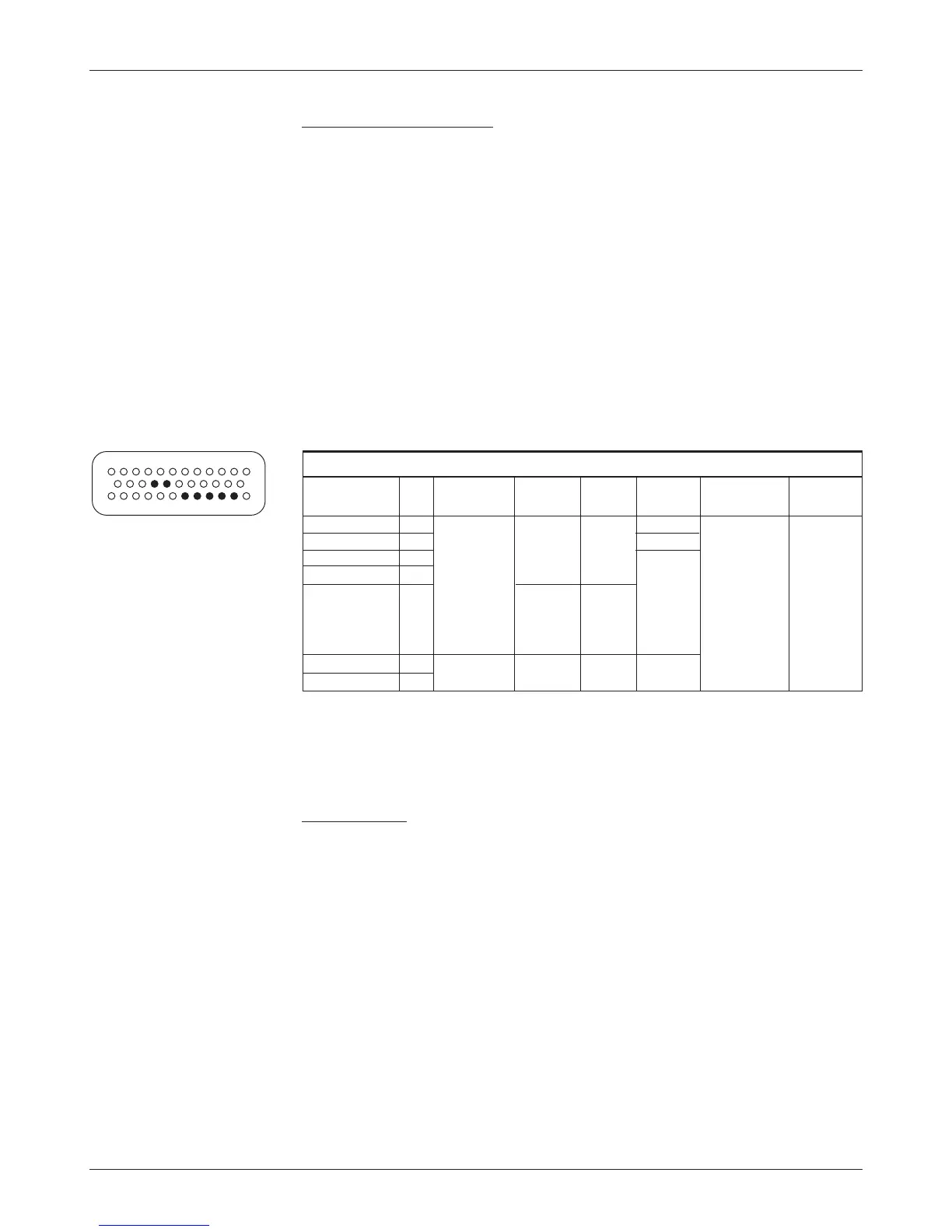
DIGITAL AND PWM OUTPUT SPECIFICATIONS
pv freq- output protected esd
signal name pin pwm
current uency current voltage tolerance
Driver1 6 0to100% n/a 120to 2Amax - 0.5Vto ± 8kV
Driver2 5 dutycycle 1000 Hz 3Amax (MaxV + 10 V) (direct strike)
Driver 3 4 * 2 A max
Driver 4 3
PropDriver 2 0to2A 18kHz
in 607
nominal
steps
Digital Out 6 19 on/off n/a n/a 1 A max
Digital Out 7 20
* Drivers 1–4 frequency is set by
the PWM Frequency parameter.
Analog inputs
Two control lines can be used as analog inputs. Both inputs are protected
against shorts to B+ or B-.
Typically Analog 2 is used as the input for the motor temperature sensor.
is input provides a constant current appropriate for a thermistor sensor. Some
standard predened motor temperature sensors are supported in software (see
Sensor Type parameter, page 63). Note: e industry standard KTY tempera-
ture sensors are silicon temperature sensors with a polarity band; the polarity
band of a KTY sensor must be the end connected to I/O Ground (pin 7).
ese lines can also be used as digital inputs, and are included in that
group as well (see page 19).
Digital and PWM outputs
Seven output drivers are available. One of these, the proportional driver, can be
operated in a current control mode for driving a proportional valve or similar
load. e frequency of this driver is normally 18 kHz, but this output can also
serve to drive an electronic speedometer or tachometer using the VCL function
Automate_Frequency_Output(); see page 133.
Each output can be independently turned on continuously (low level)
or pulse width modulated to set the average output voltage. ese outputs
are intended to drive inductive loads such as contactors and electromagnetic
brakes but could also be used to drive resistive loads if peak current ratings are
not exceeded. All these outputs are protected against shorts to B+ or B-. All
inductive loads should be connected to the coil return (pin 13), which provides
yback diode protection. ese lines can also be used as digital inputs, and are
included in that group as well.