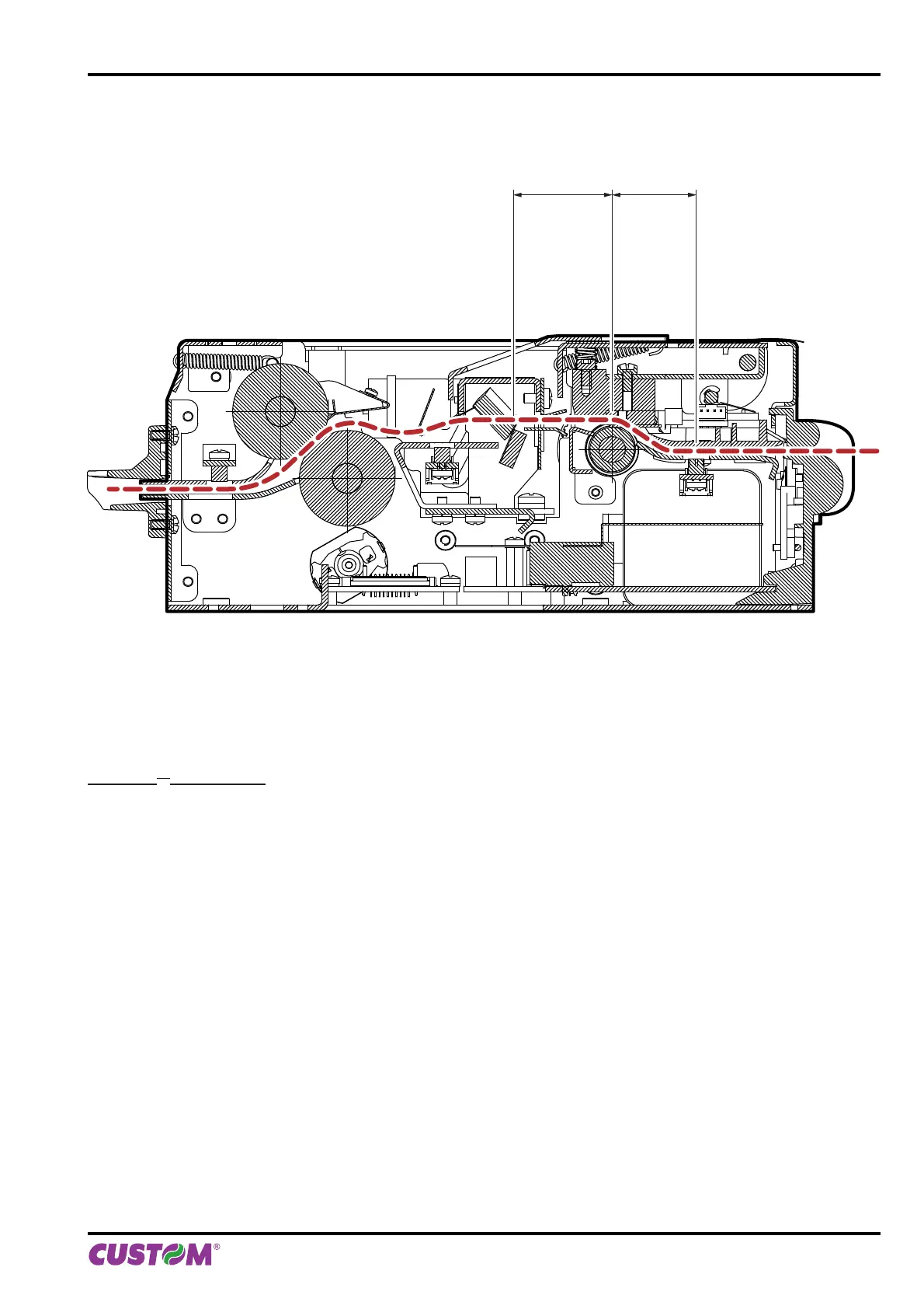
The following fi gure shows a section of the device with the paper path and the distances (in mm) between the align-
ment sensor, the printing head and the cutter (cutting line).
Printing head
Notch sensor
25.5
Autocutter
30
ESC/POS
TM
EMULATION
To d efi ne the alignment point you need to set the printer parameters that compose the numerical value of the “Notch
Distance” parameter. (see par.5.4).
For example, to set a notch distance of 15mm between the notch and the alignment point, the parameters must be
set on the following values:
Notch Distance Sign : +
Notch Distance [mm x 10] : 1
Notch Distance [mm x 1] : 5
Notch Distance [mm x .1] : 0
The “Notch Distance” parameter, may be modifi ed as follows:
• during the Setup procedure of the device (see chapter 5)
• by modifying the Setup.ini fi le (see par.12.9)
• by using the $1D $E7 command (for more details, refer to the Commands Manual)
• by driver
10. ALIGNMENT
User manual KPM216HII ETH 89