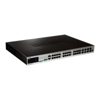
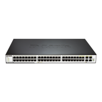
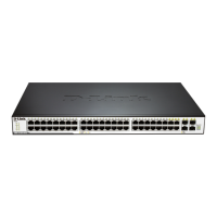
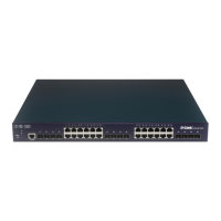
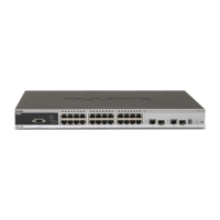
xStack DGS-3400 Series Layer 2 Gigabit Ethernet Managed Switch
38
Duplicate Address Detection (DAD)
DAD messages are used to specify that there is more than one node on a local link possessing the same IP address. IPv6 addresses
are only leased for a defined period of time. When that time expires, the address will become invalid and another address must be
addressed to the node. To ensure that this new address is unique on the local link, a node runs a DAD process to determine the
uniqueness of the new address. This is done through the use of a Neighbor Solicitation message containing a Tentative address.
This message will detect if another node on the local link has this Tentative address. If the Tentative address is found on another
node, that node will send out a Neighbor Advertisement message, the process will be terminated, and manual configuration will be
necessary. If no answer is forthcoming regarding this Neighbor Solicitation message containing the tentative address, the address
is allotted to the node and connectivity is established.
Assigning IP Addresses
For IPv4 addresses, users may only assign one address per interface and only one address may be used on a particular VLAN. Yet,
IPv6 addresses are different. All IPv6 interfaces on the switch must have at least one IPv6 link-local unicast address, if the user is
employing the IPv6 addressing scheme. Multiple IPv6 addresses may be configured for IPv6 interfaces, regardless of type,
whether it is unicast, multicast or anycast. The scope of the address has some bearing on the assigning multiple addresses to a
single interface as well. If multiple physical interfaces are considered as one interface on the Internet layer, multiple unicast
addresses may be alloted to multiple physical interfaces, which would be beneficial for load sharing on these interfaces. This is
dependent on these unicast addresses having a scope smaller than the link-local address, if these unicast addresses are not the
source or destination address for IPv6 packets to or from address that are not IPv6 neighbors of the interface in question.
IP Interface Setup
Each VLAN must be configured prior to setting up the VLAN’s corresponding IP interface.
An example is presented below:
VLAN Name VID Switch Ports
System (default) 1 5, 6, 7, 8, 21, 22, 23, 24
Engineer 2 9, 10, 11, 12
Marketing 3 13, 14, 15, 16
Finance 4 17, 18, 19, 20
Sales 5 1, 2, 3, 4
Backbone 6 25, 26
Table 6- 1. VLAN Example - Assigned Ports
In this case, six IP interfaces are required, so a CIDR notation of 10.32.0.0/11 (or a 11-bit) addressing scheme will work. This
addressing scheme will give a subnet mask of 11111111.11100000.00000000.00000000 (binary) or 255.224.0.0 (decimal).
Using a 10.xxx.xxx.xxx IP address notation, the above example would give six network addresses and six subnets.
Any IP address from the allowed range of IP addresses for each subnet can be chosen as an IP address for an IP interface on the
switch.
For this example, we have chosen the next IP address above the network address for the IP interface’s IP Address:
VLAN Name VID Network Number IP Address
System (default) 1 10.32.0.0 10.32.0.1
Engineer 2 10.64.0.0 10.64.0.1
Marketing 3 10.96.0.0 10.96.0.1
Finance 4 10.128.0.0 10.128.0.1
Sales 5 10.160.0.0 10.160.0.1
Backbone 6 10.192.0.0 10.192.0.1
Table 6- 2. VLAN Example - Assigned IP Interfaces
The six IP interfaces, each with an IP address (listed in the table above), and a subnet mask of 255.224.0.0 can be entered into the
Setup IP Interface window.
 Loading...
