5-23
EMS(Engine Management System)
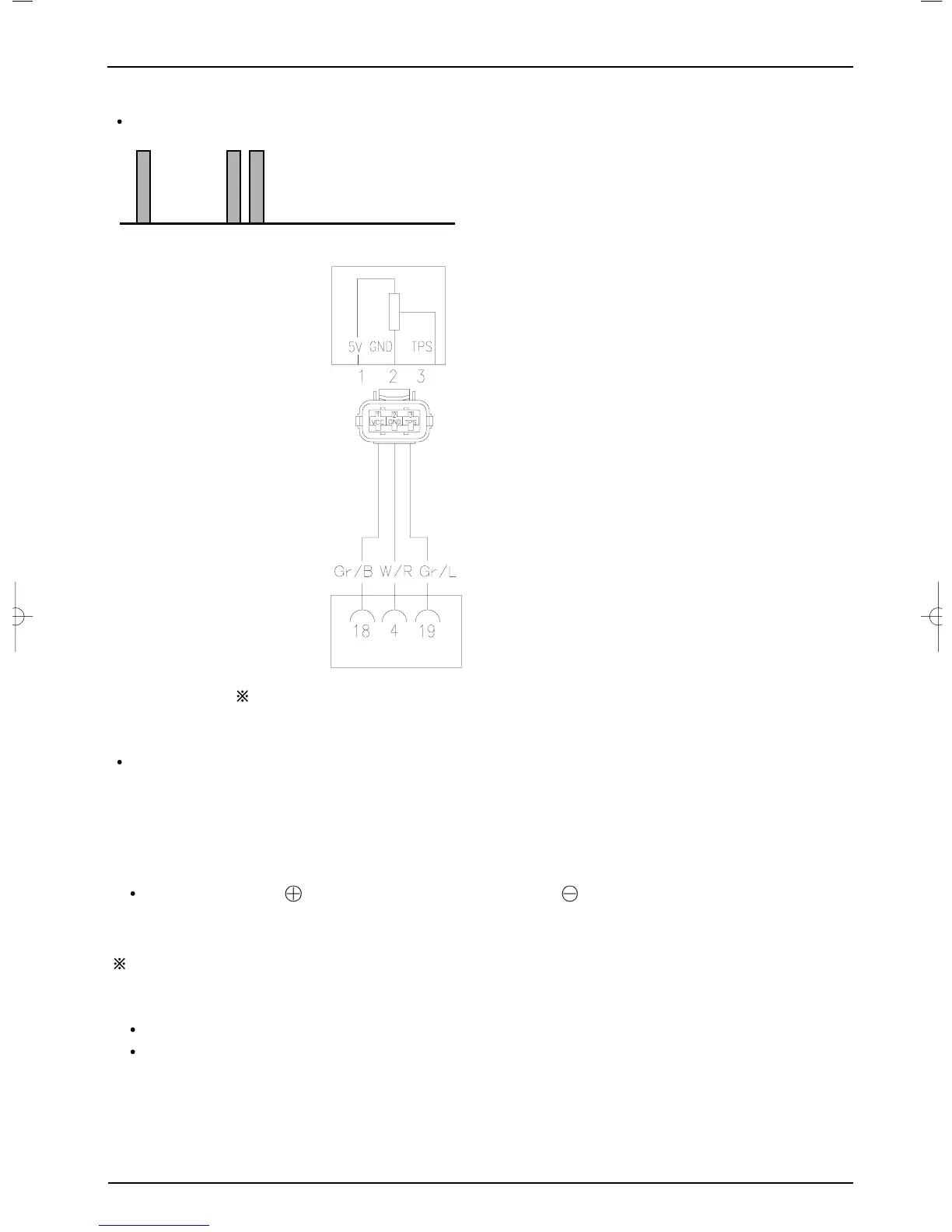
CHECKING THE TPS(Throttle Position Sensor) CIRCUIT DIAGRAM
Fault code number is displayed by MIL
Checking circuit
The coupler terminal is based on the side of wire-harness
Checking Procedure
1) Turn off ignition key .
2) Check the TPS(Throttle Position Sensor) coupler is loose, or bad.
If there is no defect, measure the input voltage of TPS.
3) Disassemble the TPS coupler
4) Turn on the IGNITION KEY.
Measuring terminal : ECU NO.18(Gr/B : GRAY/BLACK) ~ ECU NO.4 (W/R : WHITE/RED)
Measure the terminal voltage of TPS’s coupler.
Measuring voltage : 4.5[V] ~ 5.5[V]
Remarks : Measuring unit of voltage : voltage [V]
If voltage value is not normal,
Check to see if the ECU coupler is loose if there is bad contact.
Check the ‘GR/B’’ electric wire, ‘W/R’ electric wire, ‘GR /L’ electric wire to see if they have been
broken or have short- circuited.
5) If the value of voltage is normal, turn off the ignition key.
 Loading...