5-26
EMS(Engine Management System)
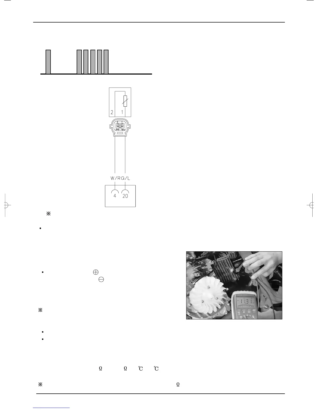
1)CHECKING THE CIRCUIT DIAGRAM OF ETS(Engine Temperature Sensor)
●Fault code number is displayed by MIL
CHECKING CIRCUIT
Coupler terminal is based on the side of wire-harness
Checking Procedure
1) Turn off the ignition key .
2) Check the ETS(Throttle Position Sensor) coupler is loose, or bad.
If there is no defect, measure the input 5 voltage of ETS.
3) Disassemble the coupler of ETS
4) Turn on ignition key.
Measuring terminal : ECU No. 20 (Gr/L: GREEN/BLUE)
~ ECU No.4 (W/R : WHITE/RED)
Measure the terminal voltage of ETS’s coupler.
Measuring voltage : 4.5[V] ~ 5.5[V]
Remarks : Measuring unit for voltage : voltage [V]
If the voltage value is not normal,
Check to see if the ECU coupler is loose if there is bad contact.
Check the ‘G/L’’ electric wire, ‘W/R’ electric wire, ‘W/R’ electric wire to see if they have been
broken or have short- circuited.
5) If the voltage value is normal, turn off the ignition key.
6) Disassemble the coupler of ETS, and measure the resistance of ETS.
Resistance of ETS :1.6[k ]~10.6[k ],20 ~80
Measuring terminal : Each terminal of ETS
Remarks : Measuring unit for resistance : Resistance ‘ R ‘ [k ]