SiEN18-622 Wiring Diagrams
Appendix 423
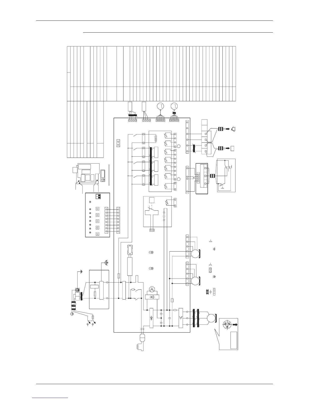
RMXS112/140/160EV1A, RMXS112/140/160EVLT
C4
X2M
A2P
A3P
A4P
L1R
X1M
2. : Field wiring.
V3R
Notes)1. This wiring diagram isapplied only to the outdoor unit.
6. When operating, don’t short circuit for protection device. (S1PH)
9. When using the central control system,connect outdoor-outdoor transmission F1 · F2.
3. : Terminal strip
: Terminal
4. When using the option adapter refer to the installation manual.
7. Color BLU:Blue - BRN:Brown - GRN:Green - RED:Red - WHT:White YLW: Yellow ORG:Orange.
R1
X37A
(Front)
HBP
El, compo, box
HAP
(Back)
A1P
Air control
L
V1T
S2S
Heat
N
S1NPL
X21A
Y2S
R2T
t°
Z
2
F
B
BRN
LE
R3T
M
+
S2S
H6P
N=1
U
E
ORG
R7T
Y1S
X66A
X2M
R6T
X37A
Note) 4
BS2
K2R
Y2S
F1U
U
M2F
-
Note) 8
M1C
PS
V
Y1E
Z2C
Y1S
To BP unit
Y3S
OFF
L
R2
W
M
E1HC
Cool
V1R
C1~4
RED
H4P
Y1E
S1NPH
F1
L1R
HAP
t°
C1
X111A
Note) 9
A3P
R4T
1 X13A
NB
+
A2P
Z4F
Noise filter
K5R
X32A
C
V1R
X2M
Z1C~7C
FAN
HBP
F2
C3
S1S
K1M
BP Unit
(F1)(F2)
+
BS1~5
X1A
N-BluL-Red
Y3S
FINTH
WHT
BS5
K1R
12
K5R
R2T
LD
X27A
S1PH
LC
V2R
RED
F4U
X2A
MS
3~
H1P
R1
Z3C
N=1
Y3E
Z6C
N
RED
R7T
BS4
X1M
+
V1T
HBP
P<
Z4C
N=1
GRN
R5T
X1M
A
N=6
ORG
BLU
R5T
GRN/YLW
t°
Cool/Heat selector
WHT
L1R
Noise filter (ferrite core)
F2
6
W
H3P
K3R
1 X12A
LB
R3T
t°
K3R
X1M
t°
F1U,F4U
A4P
YLW
Z3F
F6U
F6U
Outdoor
(F1)(F2)
X28A
R4T
+
+
X1M
R2
F1
X81A
R1T
DS1
X11A
GRY
X22A
A1P
K1R
K2R
FIN
TH
S1S
BLU
C2
BS1
N=1
WHT
NC
HAP
H1P~8P
t°
LA NA
+
Z1F
Z1C
X5A
Y3E
M1F
PS
Z7C
N=1
E1HC
V
Z1F~4F
X106A
P
A1P
N
-
H8P
6
V2R, V3R
X26A
BLU
H7P
ON
A2P
A3P
A4P
H2P
C/H Selector
t°
MS
3~
C4
K4R
R6T
MS
3~
R1T
S1NPH
S1NPL
BLU
M2F
M1C
Power supply
V1A : 220-240V~50Hz
VLT : 220V~60Hz
RED
K4R
X37A
Note) 4
H5P
X205A
BS3
-
K1M
X107A
M1F
X25A
Z5C
N=4
S1PH
t°
X18A
X17A
DS1
UWV
3D051732C
: Movable connector
: Fixed connector
: Protective earth (screw)
: Noiseless earth
To out/D unit
Solenoid valve (4 way valve)
Solenoid valve (Hot gas)
Solenoid valve (U/L circuit)
C/H Selector
Selector switch (fan/cool·heat)
Selector switch (Cool/Heat)
Connector of option adaptor
Connector
(Option adaptor power supply)
Printed circuit board (Main)
Printed circuit board (Service)
Printed circuit board (Noise filter)
Printed circuit board (C/H Selector)
Push button switch
(Mode, Set, Return, Test, Reset)
Capacitor
Dip switch
Crankcase heater
Fuse (T 6.3A/250V)
Fuse (T 5.0A/250V)
Pilot lamp (Service monitor-orange)
[H2P]Prepare, test ------ Flickering
Malfunction dedection - Light up
Operation pilot lamp
(Service monitor - green)(A1P)
Inv. pilot lamp
(Service monitor - green)(A1P)
Magnetic contactor
Magnetic relay (Y1S)
Magnetic relay (Y2S)
Magnetic relay (Y3S)
Magnetic relay (E1HC)
Magnetic relay
Reactor
Motor (Compressor)
Motor (Fan) (Upper)
Motor (Fan) (lower)
Power supply
Resistor
Resistor
Thermistor (Air)
Thermistor (M1C Discharge)
Thermistor (Suction1)
Thermistor (coil)
Thermistor (Suction2)
Thermistor (subcool)
Thermistor (Liquid)
Thermistor (Fin)
Pressure sensor (High)
Pressure sensor (Low)
Pressure switch (High)
Power module
Diode module
Terminal strip (Power supply)
Terminal strip (Control)
Terminal strip (C/H Selector) (A4P)
Electronic expansion valve (Main)
Electronic expansion valve (Sub cool)
IGBT
The position of
compressor
Terminal
The entrance
of wire
5. Refer to ‘operation caution label’ (on back of front plate) how to use
BS1
~
BS5 and DS1 · 2 switch.
8. Refer to the installation manual, for connection wiring to
BP-outdoor transmission F1 · F2.