Figure 4-214 Spring Pin Identification
3. Replaceanydefectivespringpins(bentpinheadorinconsistentheightontopwithothers)withnew
ones.Onlydothiswhenabsolutelynecessary.Whenremovingthespringpins,usesmallneedle-nose
pliersandgentlypullstraightupwithnolateralmovement.
NOTE
Donotattempttostraightenorrepairanydamagedspringpins.Thedefectivepinsmustbereplaced.
4. DiscardthedefectivespringpinsandinspecttheInverterforanyforeignobjects.
5. Insertthenewspringpinscarefullyandverifytheylineupinthenotches.RefertoFigure4-212Seated
SpringPinsonpage190.
6. RetrievethenewDriverBoardfromthepackaging.
NOTE
Useextremecarewhenremovingthenewdriverboardandcoverfromthepackaging.Thecoversnapsintoplaceoverthedriverboard
butcouldseparate.Besuretoholdbothtoavoiddroppingthedriverboardifseparationoccurs.Iftheydobecomeseparated,carefully
snapthecoverbackintoplacepriortoassembly.
7. Forproperalignment,inserttwo(2)ofthefastenersinoppositecornersoftheDriverBoard.
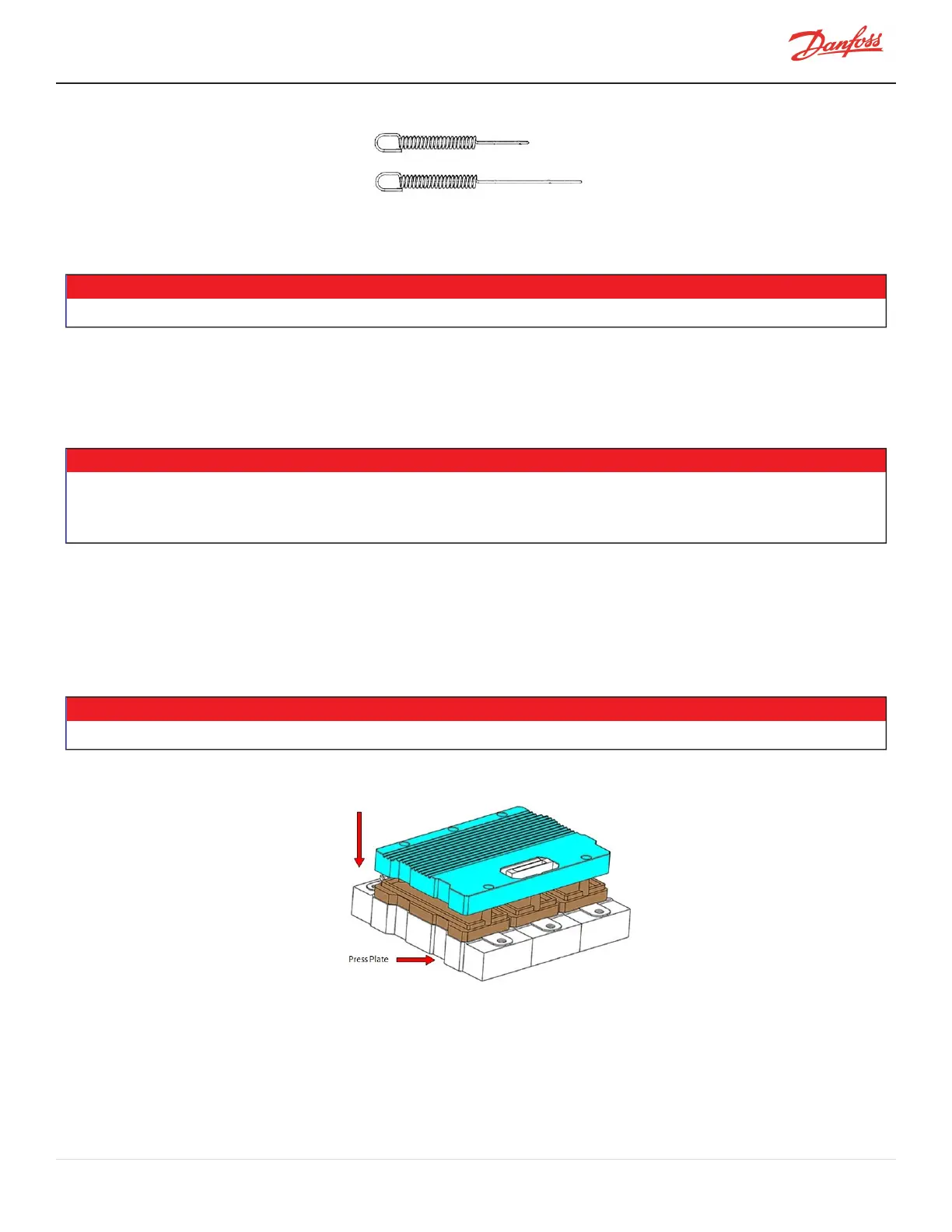
8. AlignthenewDriverBoardovertheInvertermodulewiththeconnectortowardsthemotoroutputbus
bar(theshapeofDriverBoardmustbealignedwithInverterPressPlateshape).RefertoFigure4-215
DriverBoardPlacementforthenexttwo(2)steps.
9. LowertheDriverBoarddownontheInvertermodule,donotallowforanylateralmovement.Besure
thebottomoftheDriverBoardisparallelwiththePressPlate.
• • • CAUTION • • •
Anylateralmovementmaydamagethespringpins.
Figure 4-215 Driver Board Placement
10. InserttheremainingfastenersandtightenfromcenteroutwardaccordingtoFigure4-216Initial
TighteningPassSequenceonpage192.Thiswillbethefirstpassandthefastenersshouldonlybe
snugandnottorquedatthisstep.
M-SV-001-EN Rev. H-1/23/2023 Page 191 of 294