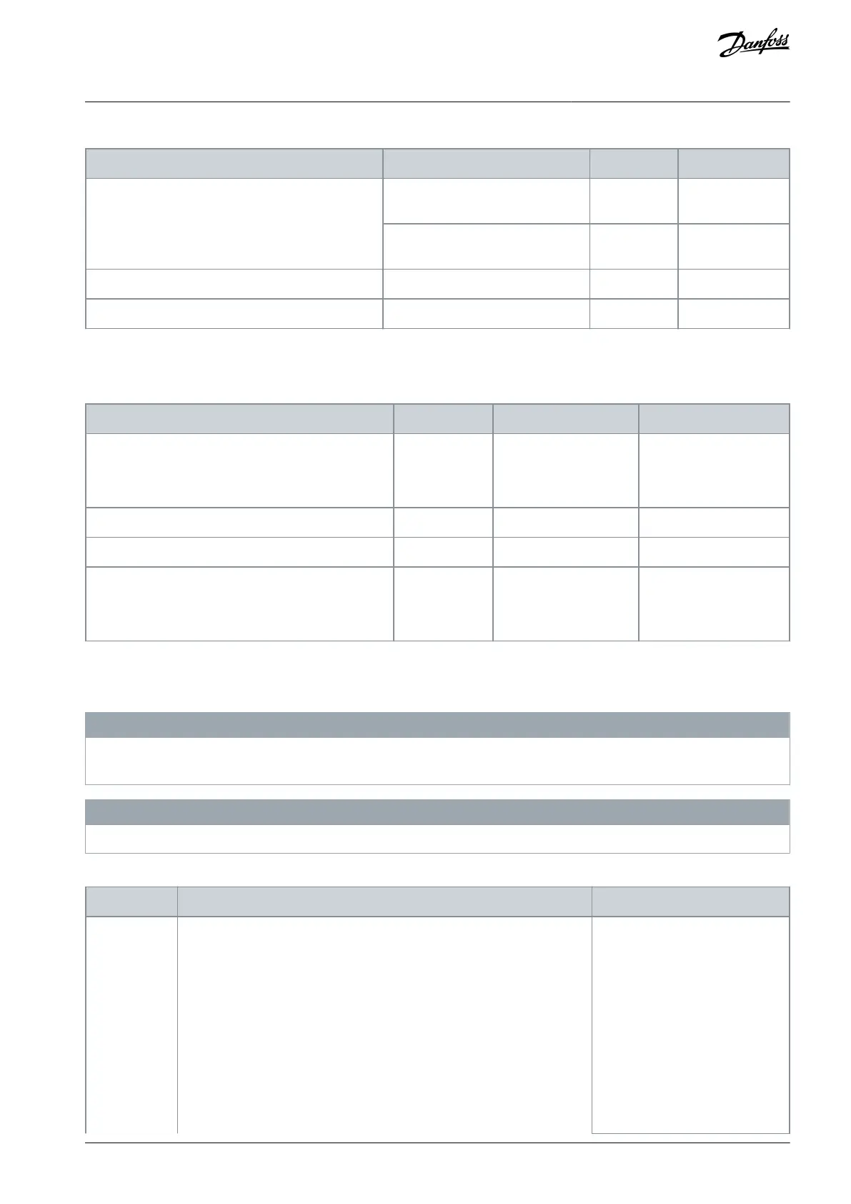
Table 40: The State of the SSM Safe Output
SSM requested (request active, even after a violation)
Actual speed inside the allowed
range
Actual speed outside the allowed
range
SSM not requested (request not active)
The table below shows the behavior of signals SSM Below Min Limit and SSM Above Max Limit that indicate which limit the speed
has crossed.
Table 41: Possible Combinations and the Results of the SSM Function
SSM Min Limit ≤ actual speed ≤ SSM Max Limit
or
SSM Min Limit ≤ actual speed, SSM Max Limit = 0
actual speed > SSM Max Limit
actual speed < SSM Min Limit
SSM not active
or
Fatal/Resettable Fault
6.3.5.4 The SSM Signals
It is possible that the Active and Reached signals that are mentioned in this chapter are not always available in all interfaces.
N O T I C E
The availability of the signals over safe fieldbus depends on the used fieldbus protocol. Refer to chapter Safe fieldbuses for more
information.
N O T I C E
The SSM signals are updated during the operation of the STO function, and during the violations of other safety functions.
Table 42: The SSM Signals
Activation and deactivation of the signal
Activation:
SSM is requested and starts execution.
Deactivation (manual acknowledgment):
Acknowledgment signal received and SSM is not requested.
Deactivation (automatic acknowledgment):
SSM request ends.
Deactivation (SSM violation situations):
The signal indicates if the SSM
function is being executed.
The signal indicates if the SSM
function is being executed.
AQ319736045637en-000101 / DPD01798 | 105Danfoss A/S © 2021.06
Safety Functions
VACON® NXP Advanced Safety Options
Operating Guide