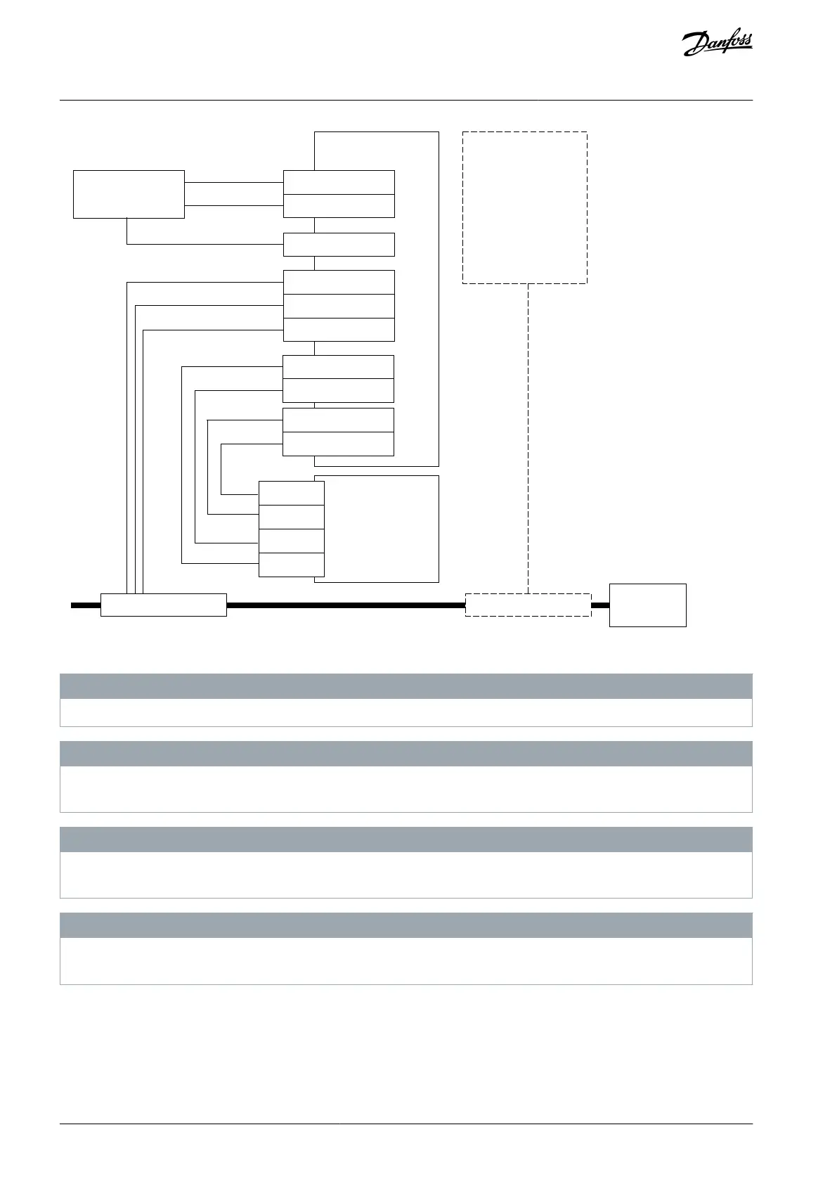
Stop switch
Relay/Contactor BrakeRelay/Contactor
X3-1 (STO 1)
X3-2 (STO 2)
X3-3 (GND)
X3-9 (+24V)
X3-10 (GND)
X3-5 (OUT1A)
X3-6 (OUT1B)
Advanced safety
option board
Other brake
controlling
systems
STO
option board
OPTAF
SD2+
SD1+
SD2-
SD1-
Illustration 78: The SS1 Function Used with the STO(+SBC) Function
N O T I C E
The example above describes a system with only one brake. It is possible that some applications require 2 brakes.
N O T I C E
The driving capability of the outputs of the Advanced safety option board is limited. Note this when you select the relay or con-
tactor connected to the output.
N O T I C E
The Advanced safety option board deactivates the STO function and the SBC function at the same time. It is possible to use other
brake controlling systems to make sure that sufficient torque has been generated to the motor shaft before the brake is released.
N O T I C E
If the execution of the ramp is safety critical, use safe speed measurement. This can be done, for example, by using an adequate
speed measurement combination on the Advanced safety option board.
13.4 SS1 Without a Direct Support of the Drive Application
If there is no suitable drive application that supports the automatic SS1 ramp, the controlled ramp down can also be based on the
external frequency reference that is supplied to the drive. When the SS1 function is requested from the drive, the speed reference is
simultaneously used to ramp the speed down.
If different systems are used to request safety functions and supply the frequency reference, the digital output of the Advanced
safety option board can be used to inform the frequency reference handling system about the SS1 request.
AQ319736045637en-000101 / DPD01798176 | Danfoss A/S © 2021.06
Configuration Examples
VACON® NXP Advanced Safety Options
Operating Guide