•
•
•
•
Table 46: Settings in the Safety PLC
The value must be the same as the F Source Address on the Advanced safety option board.
The value must be the same as the F Destination Address on the Advanced safety option board.
The value must be the same as the F WD Time on the Advanced safety option board.
The value must be the same as the final CRC of the parameter file on the Advanced safety option
board. The value can be seen in VACON
®
Safe after the verification of the parameter file is completed,
on the control panel of the AC drive, or in the commissioning report printed from VACON
®
Safe.
Safety Telegram & F-
I/O Data of the Safety
Telegram
The value must be the same as the Safety telegram in the Advanced safety option board. F-I/O Data
must be mapped as described in chapter Data mapping for PROFIdrive on PROFIsafe.
The following PROFIsafe-related parameters cannot be edited in the Advanced safety option board. They must have the same value
in the safety PLC communication to the option board over PROFIsafe. The values of the Table 47 are defined in the fieldbus GSD
description file that is provided for the fieldbus option board by VACON
®
, and must not be modified.
Table 47: The Uneditable F-Parameters
Manufacturer-specific iPar check
1 = F iPar CRC within FParameter block
Parameter block type identification
Version number of F-Parameters
Employed SIL level of F-Device
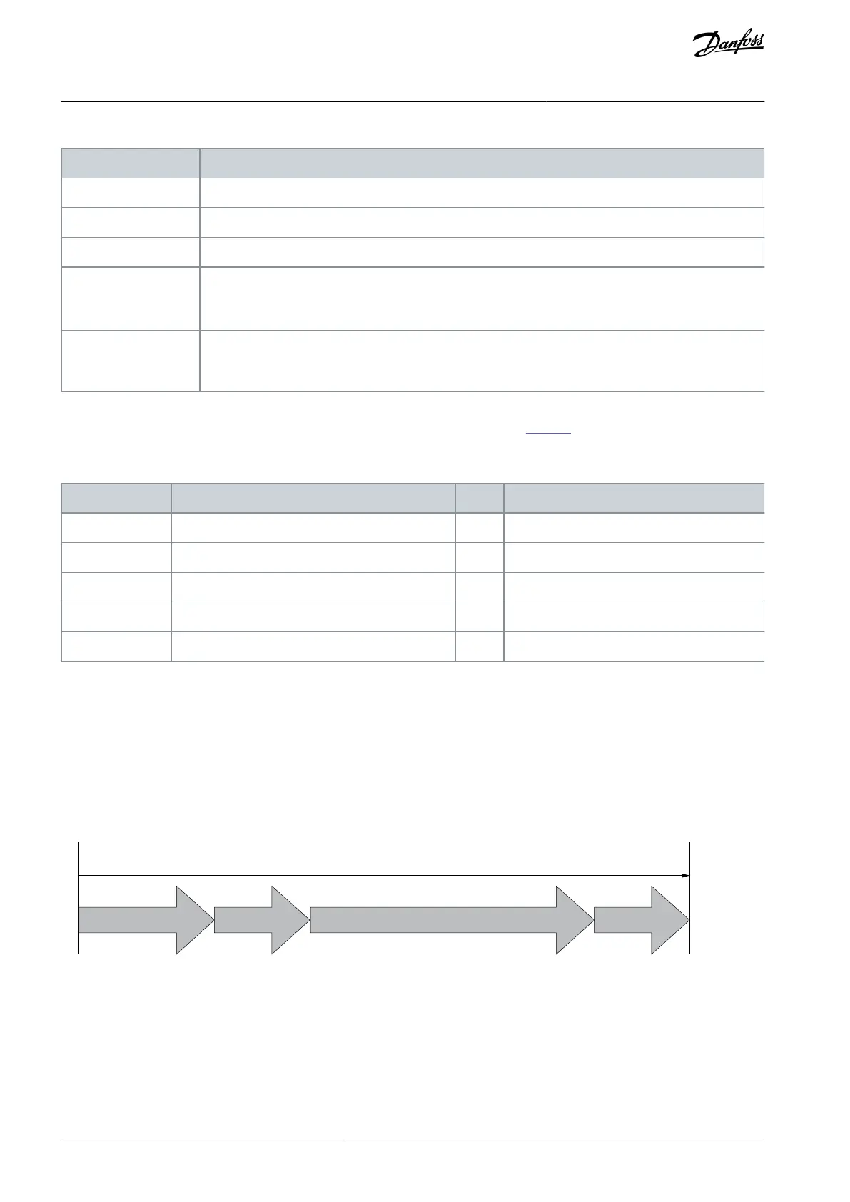
7.1.5.2 PROFIsafe Watchdog Time
Use the F-Parameter F WD Time to determine a watchdog time for the communication between F-Host and F-Device.
The minimum watchdog time has 4 parts:
DAT = Device Acknowledgment Time. F-Device receives a frame, processes it, and prepares a new frame to be sent.
Bus = The transfer time of the frame from the AC drive to F-Host.
HAT = Host Acknowledgment Time. F-Host receives a frame, processes it, and generates a new frame.
Bus = The transfer time of the frame from F-Host to the AC drive.
DAT
Bus BusHAT
F WD Time (minimum)
e30bi364.10
Illustration 71: The Parts of the Watchdog Time
It can sometimes be difficult to determine the bus transfer time that is used to calculate the watchdog time. For more information
on the cycle times, see the user guide of the used fieldbus.
Use this formula to calculate the F WD Time:
FWDTime = DAT + HAT + 2 × BT
.
AQ319736045637en-000101 / DPD01798114 | Danfoss A/S © 2021.06
Safe Fieldbuses
VACON® NXP Advanced Safety Options
Operating Guide